- FIBER OPTIC TRANSCEIVERS >200G & 100G Transceivers >100 Gb/s 120km QSFP28 Coherent Transceiver
100 Gb/s 120km QSFP28 Coherent Transceiver
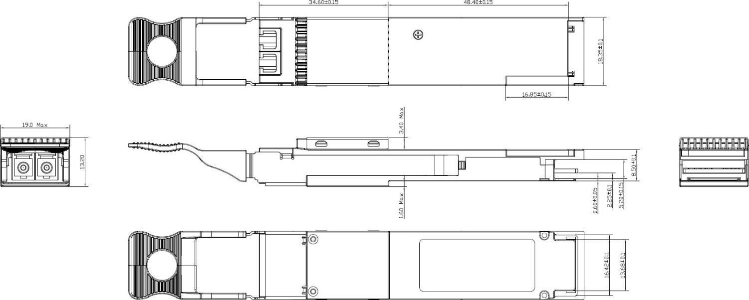
Ascent’s 100G Coherent is a 100Gbps QSFP28 optical module designed for single or multi-span DWDM links, as well as unamplified point-to-point links up to 120km. The module allows for dispersion compensation of standard single-mode fiber up to a distance of 2,000km depending on FEC mode. The product is designed with form factor and optical/electrical connection according to the QSFP28 MSA with DD and the Common Management Interface Specification (CMIS) in the OIF Coherent CMIS implementation agreement.
§ Hot-pluggable
§ Transmission reaches up to 120km in unamplified applications
§ Duplex LC connector
§ Metal package for lower EMI
§ Single 3.3V power supply
§ Maximum power consuconsumption 13W(ST), 15W(IT)
§ RoHS-6 compliant
Specifications
General Operating Characteristics
Parameter | Symbol | Min | Typ. | Max | Unit | Note |
Absolute Supply Voltage | Vcc_max | 0 | - | 4.0 | V | - |
Operating Voltage | Vcc | 3.135 | - | 3.465 | V | - |
Power Consumption | - | - | - | 13 | W | 1 |
- | - | - | 15 | W | ||
Operating Case Temperature (ST) | Top | -5 | - | 70 | °C | 2 |
Operating Case Temperature (IT) | Top | -40 | 85 | °C | - | |
Storage and Transportation Temperature | Tst | -40 | - | 85 | °C | 4 |
Relative Humidity | RH | 5 | - | 85 | 100% | 3 |
Maximum Transmission Distance (unamplified) | Dmax | - | - | 120 | km | - |
Note:
1. For SCFEC, Other modes incl. SDFEC are TBD. 13W for ST and 15W for IT.
2. Measured on top side front center of QSFP28 module.
3. Non-condensing.
Optical Characteristics
Parameter | Symbol | Min | Typ. | Max | Unit | Note |
Symbol Rate | Gbaud | - | - | 32 | GBd | - |
Modulation Format | - | DP-(d)QPSK | - | - | ||
Channel Frequency Range | - | 191.3 | - | 196.1 | THz | |
Channel Spacing | - | - | 50 | - | GHz | 2 |
Frequency Accuracy | - | -2.5 | - | 2.5 | GHz | - |
Laser Intrinsic Linewidth | LW | - | - | 300 | KHz | 4 |
Relative Intensity Noise | - | - | - | -140 | dB/Hz | - |
Note:
Transmitter Optical Characteristics
Parameter | Symbol | Min | Typ. | Max | Unit | Note |
Data rate | - | - | - | 128 | Gb/s | - |
Side Mode Suppression Ratio | SMSR | 40 | - | - | dB | - |
Tx Output Power | Pt | -8 | - | -5 | dBm | - |
Tx Output Power Monitor Accuracy | - | -2 | - | 2 | dB | - |
Tx Output Power Imbalance Between X-Pol and Y-Pol | Px/y | - | - | 2 | dB | - |
Tx XY Skew | LW | - | - | 3 | ps | - |
Tx IQ Offset | - | - | - | -24 | dB | - |
Tx IQ Imbalance | - | - | - | 1 | dB | - |
Tx Quadrature Error | - | -5 | - | 5 | degree | - |
Tx IQ Skew | - | - | - | 2 | ps | - |
Tx Error Vector Magnitude Mask Ratio | EVM | - | - | 18 | % | - |
Tx In-Band OSNR | OSNRin | 40 | - | - | dB/0.1nm | - |
Parameter | Symbol | Min | Typ. | Max | Unit | Note |
Tx Reflectance | - | - | - | -22 | dB | - |
Receiver Optical Characteristics
Parameter | Symbol | Min | Typ | Max | Unit | Note |
Rx Signal Input Power (Unamplified) | Pin | -40 | - | +5 | dBm | - |
Average Rx Sensitivity | Rsen | - | - | -32 | dBm | - |
CD Tolerance | - | - | - | 10 | ns/nm | 1 |
PMD Tolerance | - | - | - | 16 | ps | 2 |
Polarization Dependent Loss(2dB) OSNR Penalty | - | - | - | 1 | dB | - |
Rx Signal Input Power Transient Amplitude | - | -3 | - | 3 | dB | - |
State of Polarization Tracking (< 0.5dB OSNR Penalty) | - | - | 100 | KHz | ||
Rx Signal Input Power Transient Rise/Fall Time | - | 0.1 | - | ms | - | |
Rx Signal Input Power Monitor Range | - | -40 | - | +5 | dBm | - |
Rx Signal Input Power Monitor Accuracy | - | -3 | - | 3 | dB | - |
Rx Reflectance | - | - | - | -22 | dB | - |
LOS Assert | LOS A | -40 | - | - | dBm | - |
LOS De-assert | LOS De | - | - | -32 | dBm | - |
LOS Hysteresis | - | 0.5 | - | 5 | dB | - |
Metro OSNR | OSNRmin | 16.5 | - | - | dB/0.1nm | 3 |
OSNRmin | 15 | - | - | dB/0.1nm | 4 | |
LH OSNR | OSNRmin | 11.2 | - | - | dB/0.1nm | 5 |
OSNRmin | 11 | - | - | dB/0.1nm | 6 |
Notes:
1. For SCFEC. Other modes with higher CD tolerance incl. SDFEC are TBD.
2. First and second order PMD to the Maximum Mean DGD.
3. DQPSK, GFEC 7% OH, 28Gbaud, dispersion tolerance up to 100km on SMF.
4. DQPSK, SCFEC 7% OH, 28Gbaud, dispersion tolerance up to 500km on SMF.
5. QPSK, OFEC 15% OH, 31.57Gbaud, dispersion tolerance up to 2,000km on SMF, will be supported in the
near future.
6. QPSK, OFEC 15% OH, 30Gbaud, dispersion tolerance up to 2,000km on SMF, will be supported in the
near future Laser Safety: All transceivers in this datasheet are Class I Laser products per FDA/CDRH and
IEC-60825 standards. They must be operated under specified operating conditions.
Electrical Characteristics (Over Operating Case Temperature Range, Vcc = 3.14V to 3.47V)
Parameter | Symbol | Min | Typ. | Max | Unit | Note | ||
Transmitter | ||||||||
Data Rate, NRZ | - | 25.8 | - | 27.9 | Gb/s | - | ||
Differential pk-pk Input Voltage | - | 900 | - | - | mVpp | - | ||
DifferentialTermination Mismatch | - | - | - | 10 | % | - | ||
Differential Input Return Loss | - | CEI-28G VSRTP1 SDD11 | dB | - | ||||
Parameter | Symbol | Min | Typ. | Max | Unit | Note | ||
Differential to Common Mode Input Return Loss | - | CEI-28G VSRTP1 SDC11 | dB | - | ||||
Module Stressed Input Test | - | SeeOIFCEI-03.1 | - | - | ||||
Receiver | ||||||||
Data Rate, NRZ | - | 25.8 | - | 27.9 | Gb/s | - | ||
Differential Pk-Pk Output Voltage | - | 750 | - | 900 | mVpp | - | ||
AC Common Mode Output Voltage, RMS | - | - | - | 17.5 | mV | - | ||
Differential Termination Mismatch | - | - | - | 10 | % | - | ||
Differential Output Return Loss | - | CEI-28G VSR TP4 SDD22 | dB | - | ||||
Common to Diff. Mode Conversion Return Loss | - | CEI-28G VSR TP4 SDC22 | dB | - | ||||
Transition Time, 20% to 80% | - | 12 | - | - | ps | - | ||
Eye Width @1E-15 Probability (EW15) | - | 0.57 | - | - | UI | - | ||
Eye Height @1E-15 Probability (EH15) | - | 228 | - | - | mV | - | ||
Common Mode Return Loss (250MHz to 30GHz) | - | - | - | -2 | dB | - | ||
Vertical Eye Closure | - | - | - | 5.5 | dB | - | ||
Parameter | Min | Typ. | Max | Unit | Conditions |
Mgmtinit Duration | 2000 | ms | Time from power on1, hot plug or rising edge of reset until until the high to low SDA transition of the Start condition for the first acknowledged TWI transaction | ||
Reset Assert Time | 5 | us | Minimum pulse time on the ResetL signal to initiate a module reset | ||
Int/RxLOS Mode Change | 100 | ms | Time to change between IntL and RxLOSL modes of the dual- mode signal IntL/RxLOSL | ||
LPMode/TxDis Mode Change Time | 100 | ms | Time to change between LPMode and TxDis modes of LPMode/TxDis | ||
IntL Assert Time | 40 | ms | Time from occurrence of condition triggering IntL until Vout:IntL=Vol | ||
IntL Deassert Time | 500 | us | Time from occurrence of condition triggering IntL until Vout:IntL=Vol | ||
Rx LOS Assert Time | 40 | ms | Time from Rx LOS state to Rx LOS bit set(value = 1b) and IntL asserted | ||
TX Disable Assert Time | 150 | ms | Time from Tx Disable bit set to 1 until optical output falls below 10% of nominal | ||
TX Disable Deassert Time | 300 | ms | Time from Tx Disable bit cleared to 1 until optical output rises above 90% of nominal | ||
Tx Fault Assert Time | 200 | ms | Time from Tx Fault state to Tx Fault bit set(value=1b) and IntL asserted |
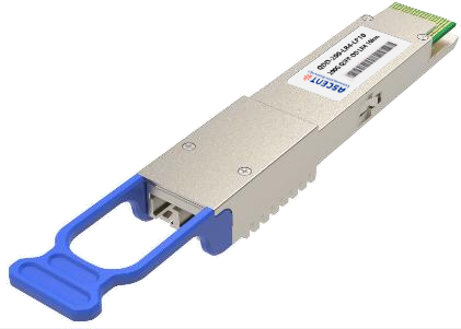
200G QSFP DD LR4 10km
200 Gb/s QSFP DD LR4 10 km Transceiver
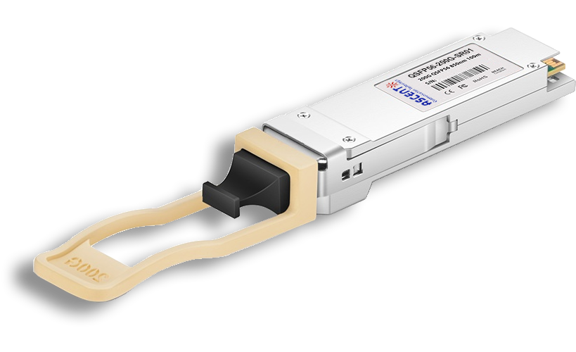
200G QSFP56 SR4 850 nm 100 m
QSFP56-200G-SR01 200 Gb/s QSFP56 SR4 850 nm 100 m Transceiver

100G QSFP28 LX4 2km
100 Gb/s 2km QSFP28 LX4 Transceiver

100G QSFP28OA LR4 10km
100 Gb/s 10 km QSFP28 LR4 Transceiver

100G QSFP28 ZR4 1310 nm 80 km
QSFP28-100G-LP80 QSFP28 100 Gbps ZR4 Transceiver
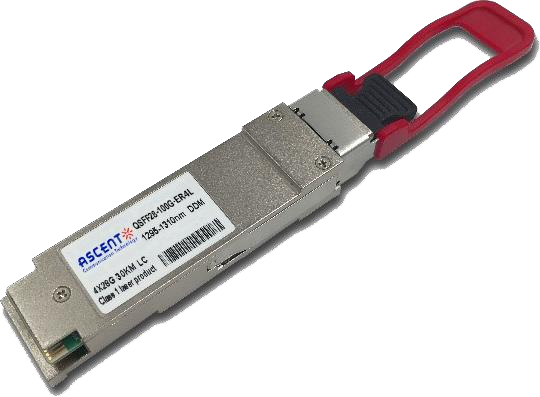
100G QSFP28 ER4L 1310 nm 40 km
QSFP28-100G-LP40 100 Gb/s 40 km QSFP28 ER4 Lite Transceiver
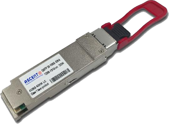
100G QSFP28 ER4 1310 nm 40 km
100 Gb/s 40 km QSFP28 ER4 Transceiver
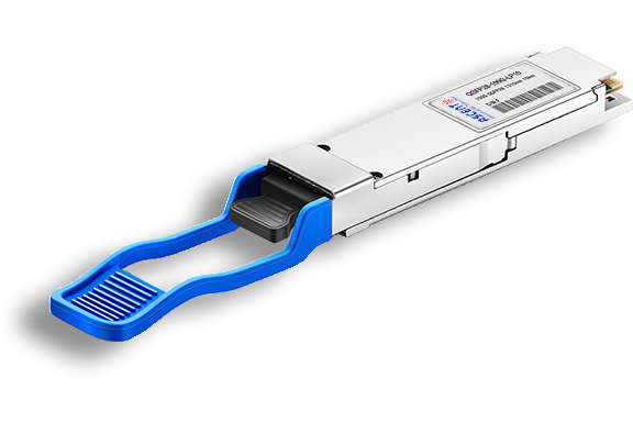
100G QSFP28 LR4 1310 nm 10 km
QSFP28-100G-LP10 100 Gb/s 10km QSFP28 LR4 Transceiver
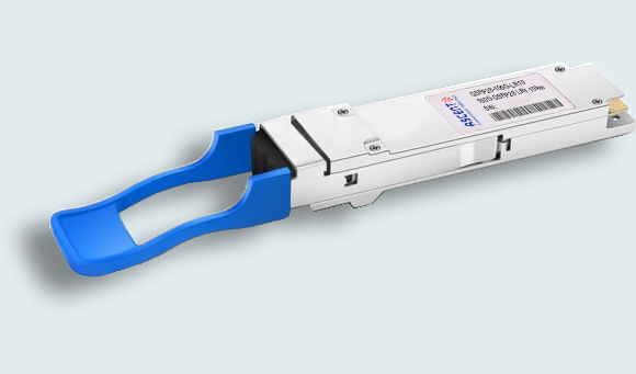
100G QSFP28 LR Single λ 10 km
100G QSFP28 LR1 10 km Single Channel

100G QSFP28 DR Single λ 500 m
QSFP28 100G DR Single Lambda Transceiver
100G QSFP28 ER4-E 1310 nm 40 km
ACT_QSFP28-100G-ER4-E
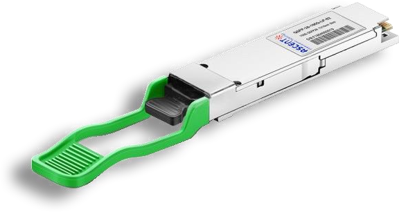
100G QSFP28 CWDM4 1310 nm 2 km
QSFP28-100G-LP02 QSFP28 100 Gbps CWDM4 Transceiver
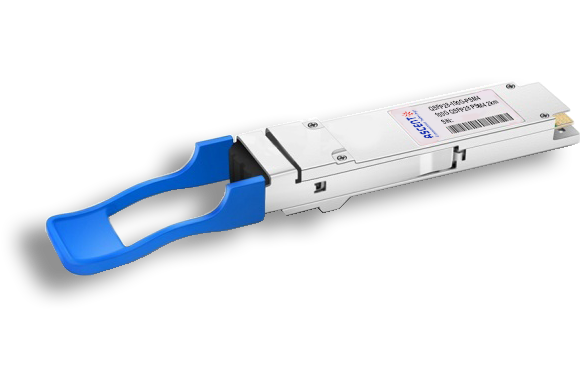
100G QSFP28 PSM4 1310 nm 2 km
QSFP28-100G-PSM4 100 Gb/s 1310 nm 2 km Transceiver
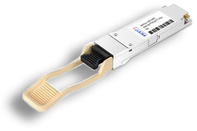
100G QSFP28 SR4 850 nm 100 m
QSFP28-100G-SR01 100 Gb/s SR4 850 nm 100 m Transceiver
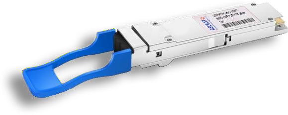
100G QSFP28 FR Single λ 1310 nm 2 km
100G QSFP28 FR 2km Transceiver

100G QSFP28 SR01 BIDI MMF 850nm 100m
QSFP28 BIDI 100 Gb/s SR Transceiver 100m

100G QSFP28 BIDI 80km
QSFP28 BIDI 100 Gb/s ZR4 Transceiver 80km

100G QSFP28 BIDI 40km
QSFP28 BIDI 100 Gb/s ER Transceiver 40km

100G QSFP28 EZR4 100km
QSFP28 100Gb/s EZR4 Transceiver 100km

100G SFP56 ER1 30km
SFP56-DD 100G-ER1 Optical Transceiver 30km

100G SFP56 LR1 10km
SFP56-DD 100G-LR1 Optical Transceiver 10km
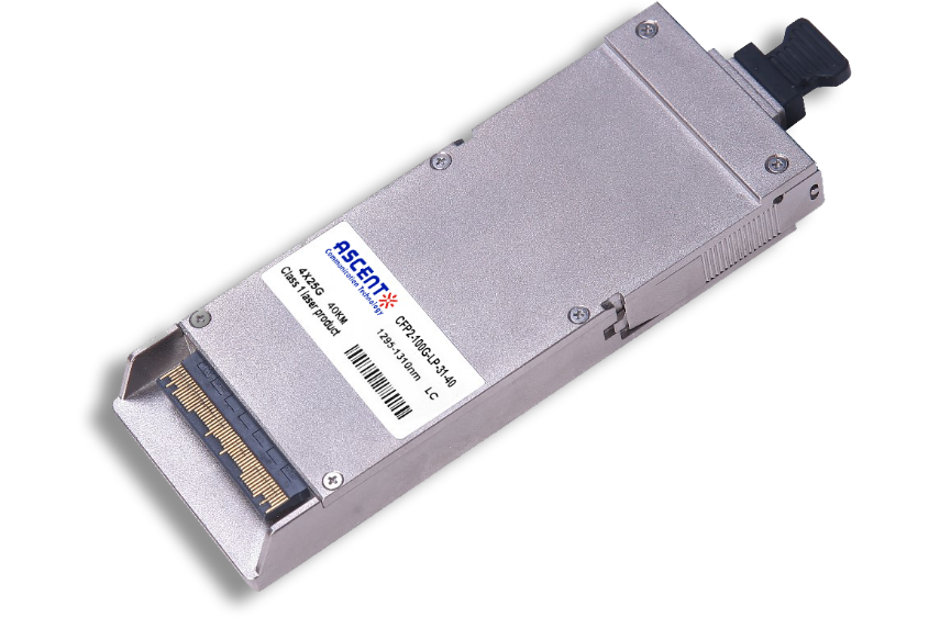
100G CFP2 ER4 40 km
CFP2-LP-31-40 100 Gb/s CFP2 ER4 40 km Transceiver
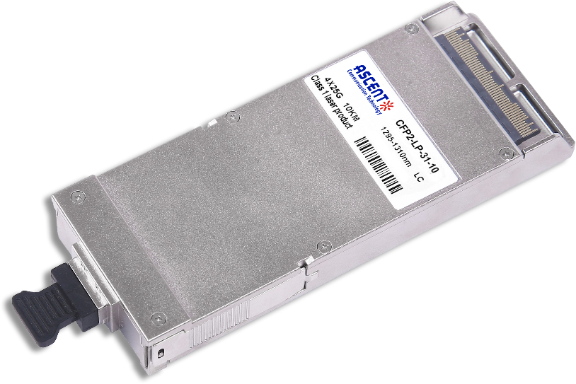
100G CFP2 LR4 10 km
CFP2-LP-31-10 100 Gb/s CFP2 LR4 10 km Transceiver
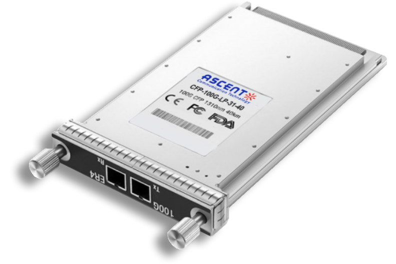
100G CFP ER4 40 km
CFP-LP-31-40 100 Gb/s CFP ER4 40 km Transceiver
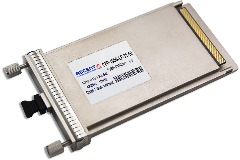
100G CFP LR4 10 km
CFP-LP-31-10 100 Gb/s CFP LR4 10 km Transceiver
White Paper
Press Releases
Briefings 1
Briefings 2
Videos, etc.
QRG
Manual1
Manual2
Get in touch with our experts
Feedback