- FIBER OPTIC TRANSCEIVERS >200G & 100G Transceivers >100G QSFP28 LR Single ö£ 10 km
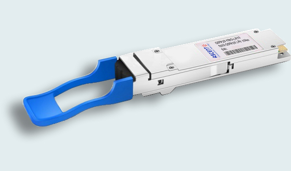
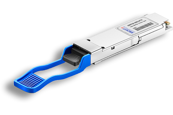
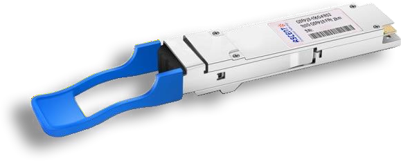
100G QSFP28 LR Single ö£ 10 km
Ascentãs QSFP28 100G LR1 Ethernet module is a transceiver module designed for 10 km optical communication applications, and it is compliant with IEEE 802.3cd and QSFP28 MSA standard. QSFP28-100G-LR10 can be used in Data Centers, High-speed interconnects within and between switches, routers and transport equipment, Server- Server Clusters, Super-computing interconnections and other network applications. This module incorporates one channel optical signal, on 1310nm center wavelength, operating at 50G baud data rate. The transmitter path incorporates an EML Driver integrated in the DSP and a cooled EML together. On the receiver path, the input optical signal is coupled to a Pin photodiode detector. It is designed with form factor, optical/electrical connection and digital diagnostic interface according to the QSFP28 Multi-Source Agreement (MSA). It has been designed to meet the harshest external operating conditions including temperature, humidity and EMI interference.
ôñ QSFP28 MSA compliant
ôñ IEEE 802.3cu compliant
ôñ Optical light source: single channel 1310nm EA-DFB LD
ôñ Optical receiver: single channel PIN photo detector
ôñ Max. power consumption 4.5 W
ôñ Up to 10 km transmission on single-mode fiber
ôñ LC connector
ôñ Single 3.3V power supply
ôñ RoHS 2.0 compliant
Absolute Maximum Ratings
It has to be noted that the operation in excess of any individual absolute maximum ratings might cause permanent damage to this module.Parameter | Symbol | Min. | Typ. | Max. | Unit | Note |
Maximum Supply Voltage | Vcc | -0.3 | 3.3 | 3.6 | V | |
Storage Temperature | Ts | -40 | 85 | ô¯C | ||
Relative Humidity | Rh | 0 | 85 | % | 1 | |
Optical Receiver Input | 5.5 | dBm | Average |
1. Non-condensing.
Operating Environments
Parameter Operating Case Temperature | Symbol Top | Min. 0 | Typ.
| Max. 70 | Unit. ô¯C | Note
|
Supply Voltage | Vcc | 3.135 | 3.3 | 3.465 | V | |
Supply Current | 1154.4 | mA | Steady state | |||
Data Rate per Lane | 25.78125 | Gbit/s | ||||
Data Rate Accuracy | -100 | 100 | ppm | |||
Link Distance with G.652 | 10 | km |
Electrical Characteristics
Parameter | Symbol | Min. Typ. Max. | Unit | Note | |
Module Supply Current | Icc | 1.212 | A | ||
Power Consumption | P | 4.50 | W | ||
Data Rate, each Lane | 25.78125 ppm ôÝ 100 ppm | GBd | |||
Transmitter | |||||
Differential Input Voltage pk-pk | Vpp | 900 | mV | ||
Common Mode Voltage Single-Ended Input Voltage Tolerance Range Differential Termination Resistance Mismatch | Vcm | -350 -0.4 to 3.3 | 2850
10 | mV V % |
At 1 MHz |
Transition Time | 12 | ps | 20%-80% | ||
Receiver | |||||
AC Common-Mode Output Voltage (RMS) | 17.5 | mV | |||
Overload Differential Voltage pk-pk | Vpp | 900 | mV | ||
Eye Width at 10-15 Probability | EW15 | 0.57 | UI | ||
Eye Height at 10-15 Probability | EH15 | 228 | mV | ||
Vertical Eye Closure | 5.5 | dB | |||
Common Mode Voltage | Vcm | -350 | 2850 | mV | |
Differential Termination Resistance Mismatch | 10 | % | |||
Optical Characteristics
Parameter Transmitter | Min. | Typ. | Max. | Unit |
Data Rate | 53.125 ppm ôÝ 100 ppm | GBd | ||
Modulation Format | PAM4 | |||
Transmitter Wavelengths | 1304.5 | 1311 | 1317.5 | nm |
Average Launch Power | -1.4 | 4.5 | dBm | |
Optical Modulation Amplitude (OMA) | 0.7 | 4.7 | dBm | |
Extinction Ratio (ER) | 3.5 | dB | ||
Side Mode Suppression Ratio (SMSR) | 30 | dB | ||
Launch Power in OMA minus TDECQ | -0.7 (ER ãË 4.5dB) | dBm | ||
-0.6 (ER < 4.5dB) | ||||
TDECQ-10log 10(Ceq) | 3.4 | dB | ||
Transmitter and Dispersion Eye Closure for PAM4, | 3.4 | dB | ||
(TDECQ) | ||||
Transmitter Transition Time | 17 | ps | ||
Optical Return Loss Tolerance | 15.6 | dB | ||
Transmitter Reflectance | -26 | dB | ||
Average Launch Power of OFF Transmitter | -15 | dBm | ||
RIN15.6 OMA (Max.) | -136 | dB/Hz | ||
Receiver | ||||
Data Rate | 53.125 ôÝ 100 ppm | GBd | ||
Modulation Format | PAM4 | |||
Receiver Wavelengths | 1304.5 | 1311 | 1317.5 | nm |
Damage Threshold | 5.0 | dBm | ||
Average Receiver Power | -7.1 | 4.0 | dBm | |
Receiver Power (OMA) | 4.2 | dBm | ||
Receive Sensitivity (OMA Outer) (Max.) | -4.5 | dBm | ||
Stressed Receiver Sensitivity (OMA Outer) (Max.)1 | -5.9+TECQ -2.5 |
dBm | ||
LOS Assert | -15 | |||
LOS De-Assert | -8.6 | dBm | ||
LOS Hysteresis | 0.5 | dB | ||
Receiver Reflectance Conditions Of Stressed Receiver Sensitivity2 | -26 | dB | ||
Stressed Eye Closure for PAM4 (SECQ), Lane Under Test | 3.4 | dB |
1. Measured with conformance test signal for BER = 2.4 x 10 - 4.
2. There test conditions are for measuring stressed receiver sensitivity. They are not characteristics of the receiver.
Digital Diagnostic Monitoring Functions
QSFP28-100G-LR10 supports the I2C based Diagnostic Monitoring Interface (DMI) defined in document SFF- 8636. The host can access real time performance of transmitter and receiver optical power, temperature, supply voltage and bias current.
Performance item | Data Address Alarm & Warning | Alarm & Warning thresholds | Monitor |
Module Temperature | Lowpage 6 | Page03 (128-135) | Lowpage (22-23) |
Module Voltage | Lowpage 7 | Page03 (144-151) | Lowpage (26-27) |
Bias Current | Lowpage (11-12) | Page03 (184-191) | Lowpage (42-49) |
Transmitter Optical Power | Lowpage (13-14) | Page03 (192-199) | Lowpage (50-57) |
Receiver Optical Power | Lowpage (9-10) | Page03 (176-183) | Lowpage (34-41) |
ESD Design
Normal ESD precautions are required during the handling of this module. This transceiver is shipped in ESD protective packaging. It should be removed from the packaging and otherwise handled in an ESD protected environment utilizing standard grounded benches, floor mats, and wrist straps.
Parameter | Threshold | Notes |
ESD of High-Speed Pins | 1KV | Human Body Model |
ESD of Low-Speed Pins | 2KV | Human Body Model |
Air Discharge During Operation | 15KV | |
Direct Contact Discharges to the Case | 8KV |

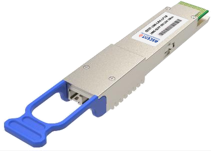
200G QSFP DD LR4 10km
200 Gb/s QSFP DD LR4 10 km Transceiver
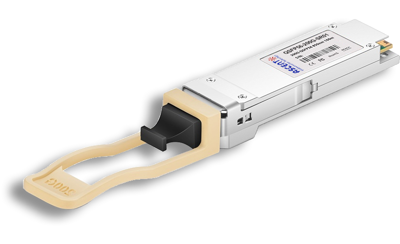
200G QSFP56 SR4 850 nm 100 m
QSFP56-200G-SR01 200 Gb/s QSFP56 SR4 850 nm 100 m Transceiver

100G QSFP28 LX4 2km
100 Gb/s 2km QSFP28 LX4 Transceiver

100G QSFP28OA LR4 10km
100 Gb/s 10 km QSFP28 LR4 Transceiver

100G QSFP28 ZR4 1310 nm 80 km
QSFP28-100G-LP80 QSFP28 100 Gbps ZR4 Transceiver

100G QSFP28 ER4L 1310 nm 40 km
QSFP28-100G-LP40 100 Gb/s 40 km QSFP28 ER4 Lite Transceiver
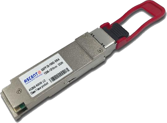
100G QSFP28 ER4 1310 nm 40 km
100 Gb/s 40 km QSFP28 ER4 Transceiver
100G QSFP28 LR4 1310 nm 10 km
QSFP28-100G-LP10 100 Gb/s 10km QSFP28 LR4 Transceiver

100G QSFP28 DR Single ö£ 500 m
QSFP28 100G DR Single Lambda Transceiver
100G QSFP28 CWDM4 1310 nm 2 km
QSFP28-100G-LP02 QSFP28 100 Gbps CWDM4 Transceiver
100G QSFP28 PSM4 1310 nm 2 km
QSFP28-100G-PSM4 100 Gb/s 1310 nm 2 km Transceiver
100G QSFP28 SR4 850 nm 100 m
QSFP28-100G-SR01 100 Gb/s SR4 850 nm 100 m Transceiver
100G QSFP28 FR Single ö£ 1310 nm 2 km
100G QSFP28 FR 2km Transceiver

100G QSFP28 SR01 BIDI MMF 850nm 100m
QSFP28 BIDI 100 Gb/s SR Transceiver 100m

100G QSFP28 BIDI 80km
QSFP28 BIDI 100 Gb/s ZR4 Transceiver 80km

100G QSFP28 BIDI 40km
QSFP28 BIDI 100 Gb/s ER Transceiver 40km

100G QSFP28 EZR4 100km
QSFP28 100Gb/s EZR4 Transceiver 100km

100G SFP56 ER1 30km
SFP56-DD 100G-ER1 Optical Transceiver 30km

100G SFP56 LR1 10km
SFP56-DD 100G-LR1 Optical Transceiver 10km
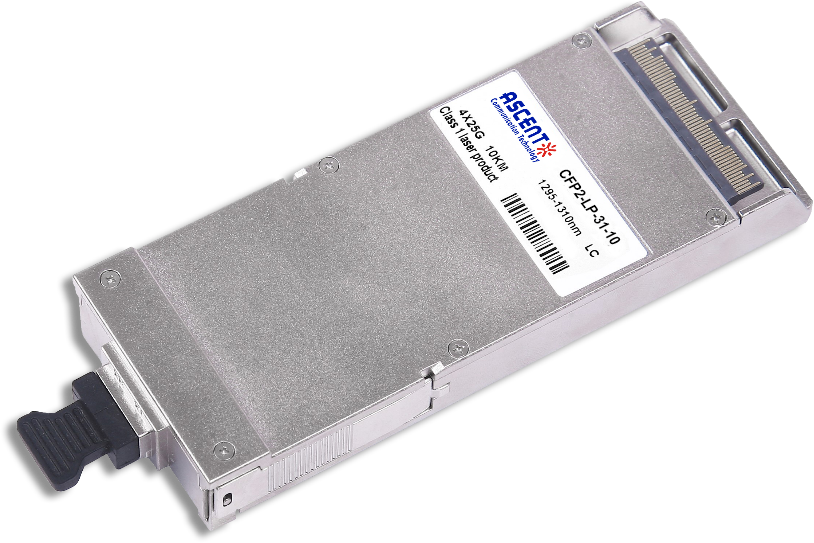
100G CFP2 ER4 40 km
CFP2-LP-31-40 100 Gb/s CFP2 ER4 40 km Transceiver
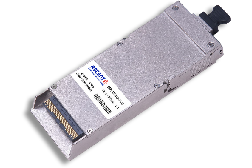
100G CFP2 LR4 10 km
CFP2-LP-31-10 100 Gb/s CFP2 LR4 10 km Transceiver
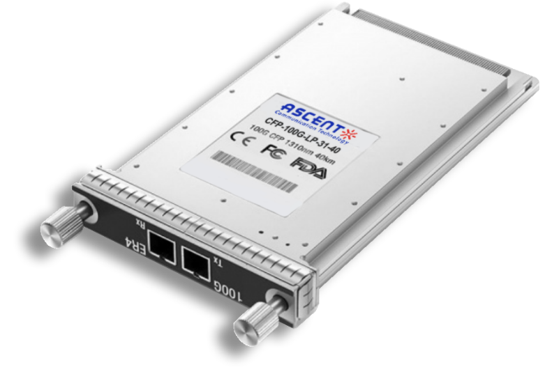
100G CFP ER4 40 km
CFP-LP-31-40 100 Gb/s CFP ER4 40 km Transceiver
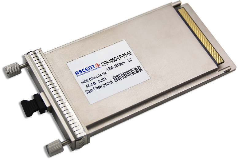
100G CFP LR4 10 km
CFP-LP-31-10 100 Gb/s CFP LR4 10 km Transceiver
White Paper
Press Releases
Briefings 1
Briefings 2
Videos, etc.
Manual1
Manual2
Get in touch with our experts
Feedback