- FIBER OPTIC TRANSCEIVERS >40G & 25G Transceivers >25G SFP28 ZR 1310nm 80km

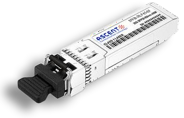
25G SFP28 ZR 1310nm 80km
Ascentãs SFP28-25LP-31-80 optical transceiver supports high-speed serial links over Single Mode (SM) optical fiber at signal rates up to 25.78 Gb/s. The product is compliant with Small Form Pluggable industry agreements SFP and SFP28 for mechanical and low-speed electrical specifications. It is intended for use in interconnect applications between data centers with switches, routers, storage equipment etc. The optical performance supports distances up to 80km. The transmitter side of the module incorporates one 1310 nm EML and CDR integrated with the EML driver to transport a 25G Ethernet signal and the receiver side is integrated with SOA and PIN- TIA followed by Rx CDR. As stipulated by the 25G Ethernet standards, Forward Error Correction (FEC) is required to be implemented by the host equipment to ensure reliable system operation. The optical parameters below will provide a bit error ratio (BER) of 5 x 10E-5 for 25G Ethernet. FEC will provide the required quality for secure service. The electrical interface is according to 25GAUI specifications per IEEE 802.3cc. Digital diagnostic monitoring information (DDMI) is present in this module per the requirements of SFF-8472, providing real- time monitoring information of transceiver laser, receiver, and environment conditions over an SFF-8419 2-wire serial interface.
ôñ Supports 25GBASE-ZR
ôñ Supports 25.78G
ôñ Up to 80km transmission on SMF
ôñ EML laser and Integrated SOA & PIN TIA rosa
ôñ High speed I/O electrical interface (25GAUI)
ôñ SFP28 MSA package with duplex LC connector
ôñ Single +3.3V power supply
ôñ Power consumption 2.5 W
ôñ Compliant to IEEE 802.3cc, SFF-8472 ver12.4 and SFF-8431
ôñ Complies with EU Directive 2015/863/EU
ôñ Operating Temperature Range:
Commercialÿ¥0ô¯C to +70ô¯C
Absolute Maximum Ratings
Parameter | Symbol | Min. | Typ. | Max. | Unit |
Storage Temperature | Ts | -40 | 85 | ô¯C | |
Operating Relative Humidity | RH | 5 | 95 | % | |
Supply Voltage | VCC | -0.3 | 3.6 | V |
Recommended Operating Conditions
Parameter | Symbol | Min. | Typ. | Max. | Unit | Notes
|
Operating Case Temperature | Tc | 0 | - | 70 | ô¯C | |
Power Supply Voltage | VCC | 3.13 | 3.3 | 3.46 | V | |
Power Supply Current | ICC | - | - | 750 | mA | |
Maximum Power Dissipation | PD | - | - | 2.5 | W | |
Bit Rate | BR | 25.78 | - | Gb/s | ||
Transmission Distance | TD | - | 80 | km | Over SMF |
Optical Characteristics
Parameter Transmitter | Symbol
| Min.
| Typ.
| Max.
| Unit | Notes
|
Center Wavelength | ö£ | 1295 | - | 1310 | nm | |
Average Launch Power | Pav | 2 | - | 7 | dBm | 1 |
Optical Modulation Amplitude | OMA | 2 | - | 8 | dBm | |
Average Output Power (Laser Turn off) | POUT-OFF | - | - | 30 | dBm | |
Side Mode Suppression Ratio | SMSR | 30 | - | - | dB | |
RIN20OMA | RIN | - | - | -130 | dB/Hz | |
Extinction Ratio | ER | 8 | - | - | dB | |
Transmitter and dispersion penalty (TDP) | - | - | 2.7 | dB | ||
Optical Eye Mask | IEEE 802.3 cc | 2 | ||||
Receiver | ||||||
Center Wavelength | ö£c | 1295 | - | 1310 | nm | |
Receiver sensitivity | RSEN | -28 | dBm | 3 | ||
LOS Assert | LOSA | -40 | - | dBm | ||
LOS De-assert | LOSD | - | - | -29 | dBm | |
LOS Hysteresis | LOSH | 0.5 | - | 5 | dB | |
Note:
1. The optical power is launched into SMF. Average launch power (min) is informative and not the principal
indicator of signal strength. A transmitter with launch power below this value cannot be compliant;
however, a value above this does not ensure compliance.
2. Measured with a PRBS 231-1 test pattern @25.78125, Hit ratioãÊ5E-5.
3. Measured with a PRBS 231-1 test pattern @25.78125 Gb/s, BERãÊ5E-5.
Electrical Characteristics
High-Speed Signal: Compliant to CEI-28G-VSR
Low-Speed Signal: Compliant to SFF-8419
Parameter | Symbol | Min. | Typ. | Max. | Unit | Notes | |
Transmitter (Module Input) | |||||||
Differential Data Input Amplitude | VIN,P-P | - | - | 900 | mVpp | ||
Differential Impedance | 90 | 100 | 110 | öˋ | |||
Tx_Disable | Normal Operation | VIL | -0.3 | - | 0.8 | V | |
Laser Disable | VIH | 2.0 | - | VCC+0.3 | V | ||
Receiver (Module Output) | |||||||
Differential Data Output Amplitude | |||||||
Differential Termination Mismatch(1MHZ) | |||||||
Differential Impedance | |||||||
Rx_LOS | Normal Operation | VOL | -0.3 | - | 0.4 | V | |
Loss Signal | VOH | 2 | - | VCCHOST | V | ||
Digital Diagnostics
Parameter | Range | Accuracy | Unit | Calibration |
Temperature | 0 to 70 | ôÝ3 | ô¯C | Internal |
Voltage | 3.13 to 3.47 | ôÝ3% | V | Internal |
Tx Bias Current Per Lane | 0 to 100 | ôÝ10% | mA | Internal |
Tx Output Power Per Lane | 2 to 7 | ôÝ3 | dBm | Internal |
Rx Power | -28 to -4 | ôÝ3 | dBm | Internal |


64G SFP56 850nm 100m
64 Gb/s SFP56 SW Fibre Channel 850nm Transceiver
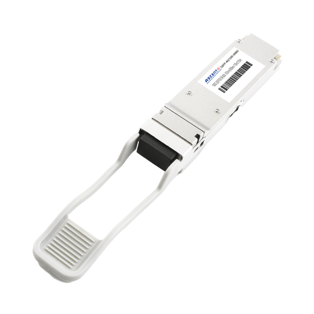
40/100G SFP28 SWDM4 100m
40/100Gb/s QSFP28, Bi-Di, Duplex LC 100m Transceiver

40G QSFP+ ER4 Industrial 40 km
40 Gb/s QSFP+ ER4 40 km Transceiver

40G QSFP+ ER4 40 km
40 Gb/s QSFP+ ER4 40 km Transceiver

40G QSFP+ LR4 Industrial 10 km
40 Gb/s QSFP+ LR4 10 km Transceiver

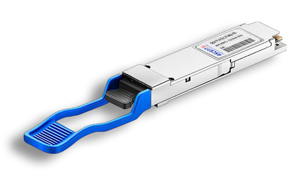
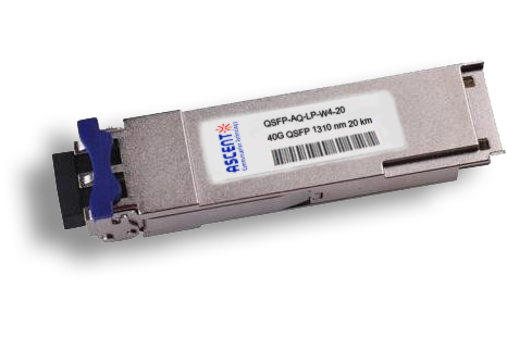
40G QSFP+ LR4 10 km
QSFP-AQ-LP-W4-10 40 Gb/s QSFP LR4 10 km Transceiver

40G QSFP+ PSM4 2 km
40 Gb/s QSFP+ PSM4 Transceiver 2km
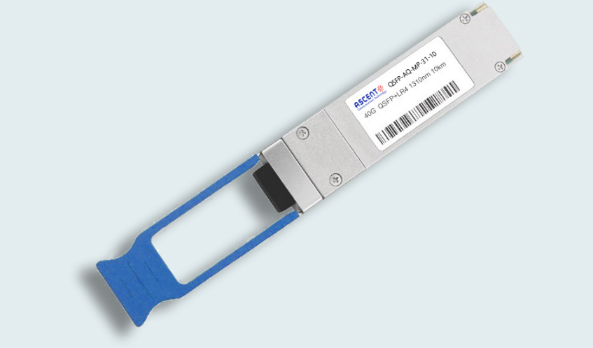
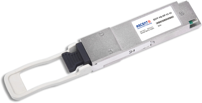
40G QSFP+ PLR4 1310 nm 10 km
QSFP-AQ-MP-31-10 40 Gb/s QSFP+ PSM 1310nm 10km MPO Optical Transceiver
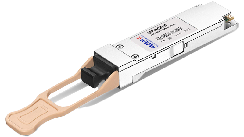
40G QSFP+ CSR4 300m
40 Gb/s 300m QSFP+ CSR4 Transceiver
40GBASE-UNIV QSFP+ MMF and SMF
40G QSFP+ UNIV MMF/SMF 150m/2km
40G QSFP+ CWDM 2 km
40G QSFP+ CWDM 2 km
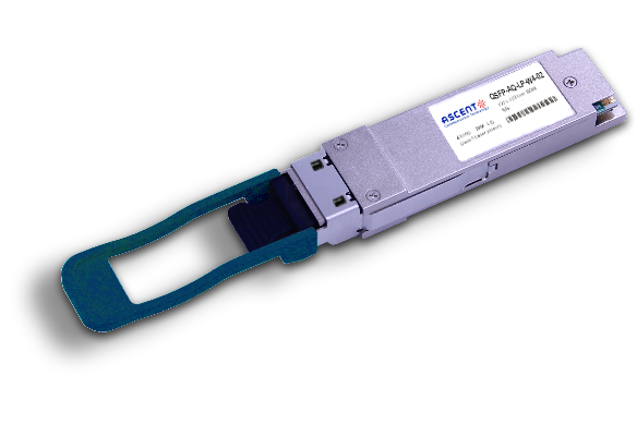
40G QSFP CWDM 20 km
QSFP-AQ-LP-W4-20 40 Gb/s QSFP CWDM 20 km Transceiver
40G QSFP+ SR4 300 m
40 Gb/s QSFP+ SR4 Transceiver with DDM

40G QSFP+ BIDI 150m
40 Gb/s QSFP+ BiDi Transceiver 150m
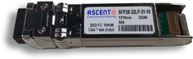
32G SFP28 1310 nm 10 km
32G FC 1310 nm 10 km SFP28 Transceiver

32G SFP28 SR 850 nm 100 m
SFP28-32LP-85-01 32GBASE-SR SFP28 850 nm 100 m DOM Transceiver
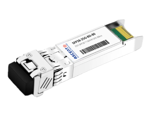
25G SFP28 BIDI 80 km
25G SFP28 BIDI 80 km Transceiver
.png)
25G SFP28 CWDM 10 km(E)
25 Gb/s CWDM EML SFP28 10 km Transceiver
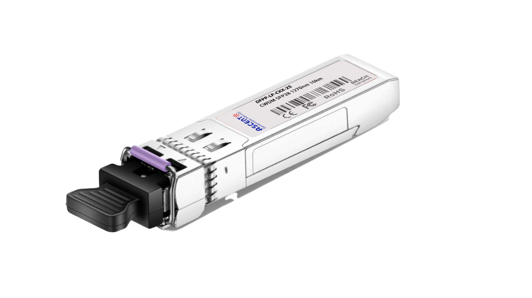
25G SFP28 CWDM 10 km(D)
25 Gb/s CWDM SFP28 10 km Transceiver
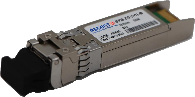
25G SFP28 1310 nm 40km
25 Gb/s 1310 nm Single-Mode SFP28 Transceiver
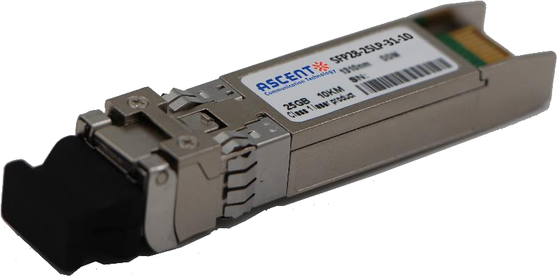
25G SFP28 1310 nm 10 km
SFP28-25LP-31-10 25 Gb/s 1310 nm Single-Mode SFP+ Transceiver
25G SFP28 850 nm 300m
25 Gb/s 850 nm Multi-Mode SFP28 300m Transceiver

25G SFP28 850 nm 100m
SFP28-25LP-85-01 28 Gb/s 850 nm Multi-Mode SFP28 Transceiver

10/25G SFP28 1310nm 40km
10/25 Gb/s SFP28 1310 nm 40km Transceiver

10/25G SFP28 1310nm 10km
10/25 Gb/s SFP28 1310 nm 10km DDM Transceiver

10/25G SFP28 850 nm 300m
10/25 Gb/s SFP28 850 nm 300m Transceiver

10/25G SFP28 850 nm 100m
10/25 Gb/s SFP28 850 nm 100m Transceiver
White Paper
Press Releases
Briefings 1
Briefings 2
Videos, etc.
Manual1
Manual2
Get in touch with our experts
Feedback