- HFC CABLE TV >RF Amplifiers >ARF120G MDU AMP
ARF120G MDU AMP
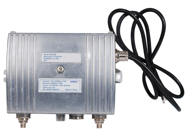
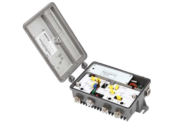
ARF120G Series 1.2 GHz GaAs amplifier is part of ACT Advanced Fiber Deep HFC solution, which has been designed to deliver interactive CATV, high capacity DOCSIS and other advanced services. The cost effective last mile amplifier platform helps operators expand bandwidth of their existing HFC network while minimizing capital investment. The ARF120G compact housing has compact housing with embedded RF module and is suitable for MDU, FTTB or FTTC applications with output up to 108 dBôçV. The ARF120G 1.2 GHz GaAs amplifier has up to 204MHz return path bandwidth with plug-in diplexers. Forward amplifier output test point can be used to insert return path carriers while monitoring the carriers signal level at the return path input test point. ARF120G amplifier has low power consumption and supports local or remote power options. Combined with ACTãs converged headend AH1000 optical system and AON node series, ARF120G is an ideal product to provide MSOs with an economical, flexible HFC access solution.
ôñ 1.2GHz forward path bandwidth
ôñ 85MHz or 204MHz return path bandwidth with plug-in diplexers
ôñ GaAs technology
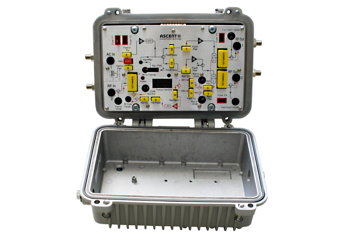
ôñ Forward path directional coupler input and output test points
ôñ Forward amplifier output test point can be used to insert return path carriers while monitoring the
carriers signal level at the return path input test point and/or the return path directional coupler input and
output test points
ôñ No additional accessories required
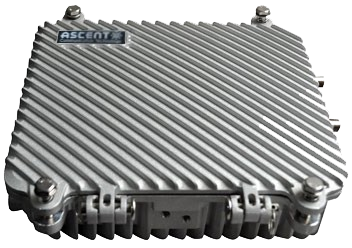
ôñ Lightweight and compact design
ôñ 6KV surge protection
Item | Unit | Technical Parameters | Note | |
Forward Path RF | ||||
Frequency Range | MHz | 105 to 1218 | 258 to 1218 | |
Gain (min.) | dB | 37 | 37 | 1 |
Frequency Response Flatness | dB | +/-0.75 | +/-0.75 | |
Reference Output Level | dBmV | 48 | 48 | |
CTB | dBc | <=-60 | <=-60 | 2 |
CSO | dBc | <=-60 | <=-60 | 2 |
Noise Figure | dB | <=8 | <=8 | 2 |
Input Attenuator | dB | 0 to 18dB variable | 0 to 18dB variable | |
Input Equalizer | dB | 0 to 18dB variable | 0 to 18dB variable | |
Interstage Attenuator | dB | 0 to 18dB variable | 0 to 18dB variable | |
Interstage Equalizer | dB | 0/7/15 selectable | 0/7/15 selectable | |
Return Loss | dB | >16 | >16 | |
Input Test Point | dB | -20 +/- 1.25 | -20 +/- 1.25 | |
Output Test Point | dB | -20 +/- 1.25 | -20 +/- 1.25 | |
Return Path RF | ||||
Frequency Range | MHz | 5 to 85 | 5 to 204 | |
Gain (min.) | dB | 27 | 27 | 1 |
Frequency Response Flatness | dB | +/-0.75 | +/-0.75 | |
IMD2 | dBc | -60 | -60 | 3 |
Noise Figure | dB | <=8 | <=8 | 1 |
Input Attenuator | dB | 0 to 18dB variable | 0 to 118dB variable | |
Output Attenuator | dB | 0 to 18dB variable | 0 to 118dB variable | |
Output Equalizer | dB | 0 to 18dB variable | 0 to 118dB variable | |
Return Loss | dB | >16 | >16 | |
Input Test Point | dB | -20 +/- 1 | -20 +/- 1 | |
Output Test Point | dB | -20 +/- 1 | -20 +/- 1 | |
General | dB | |||
Power Consumption | W | <=15 | < =15 | |
Power Supply Voltage (AC) | V | 100 to 240 | 100 to 240 | |
RF Connectors | F Female | F Female | ||
Dimensions (WxHxD) | mm | 182 x 140 x 84 | 182 x 140 x 84 | |
Weight | kg | 1.5 | 1.5 | |
Operating Temperature | ô¯C | -20 to 55 | -20 to 55 | |
Storage Temperature | ô¯C | -40 to 80 | -40 to 80 | |
Relative Humidity | % | 5 to 95 (non-condensing) | 5 to 95 (non-condensing) | |
Safety | IEC 62368-01:2018 | IEC 62368-01:2018 | ||
Surge | 6kV Combination Wave per IEEE C62.41 | 6kV Combination Wave per IEEE C62.41 | ||
1. Gain and Noise Figure measured with 0 dB input EQ and 0 dB input pad.
2. CTB and SCO are specified with 79 NTSC channels plus QAMs to 1GHz, 48dB extrapolated at 1GHz, 16dB tilt.
3. IMD speciffed with output level of 47dBmV.

ARF230 RF AMP
ARF230 High-Output Two-Way Trunk/Line Amplifier
ARF130C Trunk AMP
MDU 1 or 2 O/P Trunk Amplifier

ARF120H RF AMP
1.2 GHz RF Amplifier

ARF120C MDU AMP
1.2GHz MDU Amplifier Deep Fiber Solution
ARF120 RF AMP
ARF120B 1.2 GHz GaAs MDU Amplifier

ARF110C Trunk AMP
MDU 1 or 2 -port Line Amplifier
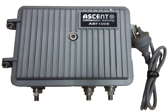
ARF100B LE AMP
ARF100B 1 or 2 RF Outputs MDU Amplifier
ARF040 RF AMP
Bi-Directional House Amplifier
White Paper
Press Releases
Briefings 1
Briefings 2
Videos, etc.
QRG
Manual1
Manual2
Get in touch with our experts
Feedback