- FIBER OPTIC TRANSCEIVERS >Optical Cables and Accessories >400G QSFP DD to 4X100G QSFP56 AOC

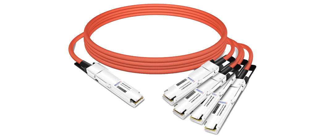
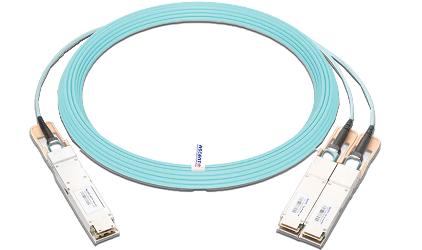
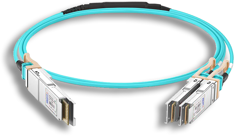
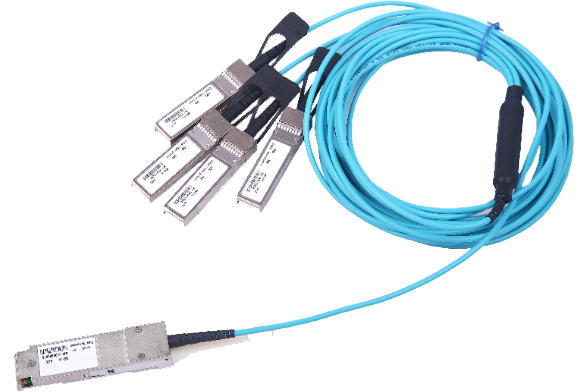
400G QSFP DD to 4X100G QSFP56 AOC
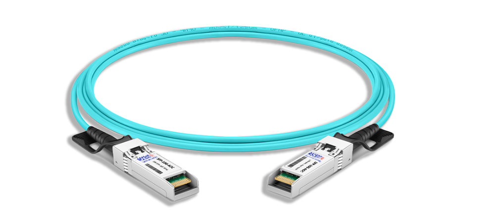
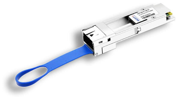
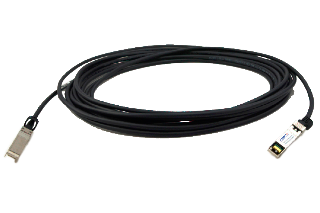
The 400G QSFP-DD to 4x100G QSFP56 breakout active optical cables are engineered for high-speed data transmission in 400 Gigabit Ethernet networks over OM3 multimode fibers. Each channel supports data rates of up to 53.125 Gbps using PAM4 modulation, delivering reliable and efficient performance for demanding applications. These cables meet critical industry standards, including IEEE 802.3db, OIF-CEI, QSFP-DD MSA, QSFP-DD-CMIS, IEEE 802.3bs Annex120E, SFF-8636, ensuring broad compatibility across various systems. With a slim and lightweight design, these breakout AOC cables facilitate simplified cable management and promote efficient system airflow, a key requirement in high-density server racks. This design helps maintain optimal cooling and performance in data-intensive environments, making these cables well-suited for modern networking infrastructures. These cables are widely utilized in cloud computing and supercomputing environments due to their low cost, high-value proposition, and proven reliability. Their combination of affordability, durability, and compliance with leading standards makes them an excellent choice for organizations seeking scalable and dependable solutions for advanced data centers.
ôñ Compliant QSFP-DD and QSFP56 MSA
ôñ Compliant with IEEE 802.3db and100G Lambda MSA
ôñ Low latency for high performance computing application
ôñ Available in standard length of 1, 3, 5, 7, 10,15, 20, 25, 30m
ôñ Operating case temperature 0 to 70ô¯C
ôñ Hot pluggable QSFP-DD and QSFP56 form factor
ôñ Power consumption<7.5W per end with QSFPDD
ôñ Power consumption<3.5W per end with QSFP56
ôñ Laser Eye Safety Class 1
ôñ Management interface based on CMIS
ôñ 4.0 and SFP-8636
ôñ RoHS compliant
Absolute Maximum Ratings
Parameter | Symbol | Min | Typ. | Max | Unit | Ref. |
Storage Temperature | Ts | -40 | - | 85 | ô¯C | |
Operating Humidity | RH | 5 | - | 85 | % | |
Maximum Supply Voltage | Vcc | -0.5 | - | 3.6 | V |
Operating Enviornment
Parameter | Symbol | Min | Typ. | Max | Unit | Note |
Supply Voltage | Vcc | 3.135 | 3.3 | 3.465 | V | |
Case Temperature | Tc | 0 | 70 | ô¯C | ||
Bit Rate as QSFP-DD end (per ch) | BR | 53.125 | Gbps | |||
Bit Rate as QSFP28 end (per ch) | BR | 106.25 | Gbps | |||
Total power consumption (QSFP-DD) | Pc | 7.5 | 10 | W | ||
Total power consumption (QSFP28) | Pc | 3.5 | 4 | W |
Electrical Characteristics for QSFP-DD end
Parameter | Min | Typ. | Max | Unit | Remarks |
Transmitter | |||||
Signaling Rate per Lane | -100 ppm | 26.5625 | +100 ppm | GBd | |
Differential Peak-to-Peak Input Voltage tolerance | 900 | mV | |||
Differential Termination Mismatch | 10 | % | |||
Single-ended Voltage Tolerance Range | -0.4 | - | 3.3 | V | |
DC common mode voltage | -350 | 2850 | mV | ||
Receiver | |||||
Signaling Speed per Lane | -100 ppm | 26.5625 | +100 ppm | GBd | |
AC Common-Mode Output Voltage RMS | 17.5 | mV | |||
Differential Peak-to-Peak Output Voltage | 900 | mV | |||
Near-End Eye Symmetry Mask Width(ESMW) (ESMW) | 0.265 0.265 | uI uI | |||
Near-End Eye Height, Differential | 70 | mV | |||
Far-End Eye Symmetry Mask Width (ESMW) |
0.2 |
uI | |||
Far-End Eye Height, Differential | 30 | mV | |||
Far-End Pre-Cursor ISI Ratio | -4.5 | 2.5 | % | ||
Differential Termination Mismatch | 10 | % | |||
Transition Time, 20 to 80% | 9.5 | ps | |||
DC Common Mode Voltage | -350 | 2850 | mV |
Electrical Characteristics for QSFP-28 end
Parameter | Min | Typ. | Max | Unit | Remarks |
Transmitter (each lane) | |||||
Signaling Rate per Lane | 25.78125 | Gb/s | |||
Differential Pk-Pk Input Voltage Tolerance (min) | 900 | - | - | mV | at TP1a |
Differential Termination Mismatch | - | - | 10 | % | at TP1 |
Single-Ended Input Voltage Tolerance Range | -0.4 to 3.3 | - | - | V | at TP1a |
DC Common Mode Voltage | -350 | - | 2850 | mV | at TP1 |
Receiver (each lane, at TP4) | |||||
AC Common-Mode Output Voltage (RMS) | - | - | 17.5 | mV | |
Differential Output Voltage | - | - | 900 | mV | |
Eye Width | 0.57 | - | - | UI | |
Eye Height, Differential | 228 | - | - | mV | |
Vertical Eye Closure | - | - | 5.5 | dB | |
Differential Termination Mismatch | - | - | 10 | % | |
Transition Time (20% to 80%) | 12 | - | - | ps | |
DC Common Mode Voltage | -350 | - | 2850 | mV |
Digital Diagnostic Specification
Parameter | Symbol | Min | Typ. | Max | Unit | Remark |
Transceiver Case Temperature | DMI_Temp | -3 | +3 | ô¯C | Over operating temp | |
Supply Voltage Monitor Absolute Error | DMI _VCC | -3% | +3% | V | Full operating range | |
Channel RX Power Monitor Absolute error | DMI_RX | -3 | +3 | dB | Per channel | |
Channel Bias Current Monitor | DMI_Ibias | -10% | +10% | mA | Per channel | |
Channel TX Power Monitor Absolute Error | DMI_TX | -3 | +3 | dB | Per channel |


OSFP 800G ACC Cable
800G Twin-port 2x400G OSFP Active Copper Cable
OSFP 800G DAC Cable
800G Twin-port 2x400G OSFP Passive DAC Cable
800G OSFP to 4x200G Breakout ACC
800G 4x200G OSFP Breakout Active Copper Cable
800G OSFP 4xQSFP112 DAC Cable
800G OSFP to 4xQSFP112 Cable Assembly
400G OSFP to 400G QSFP-DD DAC
400G OSFP to 400G QSFP-DD Passive DAC Twinax Cable

400G OSFP to 4x100G QSFP56 DAC
400G OSFP to 4x100G QSFP56 Passive DAC Breakout Cable
400G OSFP to 2x200G QSFP56 AOC Breakout Cable
400G OSFP to 2x200G QSFP56 AOC Breakout Cable

400G QSFP DD DAC Cable
400G QSFP-DD Passive Direct Attach Copper Cable

400G QSFP DD to 4X100G QSFP28 AOC
400G QSFP-DD to 4x100G QSFP28 Active Optical Cable

400G QSFP DD AOC Cable
400G QSFP-DD Active Optical Cable
400G QSFP DD AOC Breakout Cable
400G QSFP-DD to 2x 200G QSFP56 Active Optical Breakout Cable

200G QSFP56 InfiniBand HDR AOC
200G QSFP56 to QSFP56 Active Optical Cable

200G QSFP56 PSM4 DAC
200G QSFP56 PSM4 Direct Attach Passive Copper Cables
QSFP28 100G AOC Cable
100 Gb/s QSFP28 Active Optical Cable
QSFP28 100G DAC Cable
100G QSFP28 Passive DAC Twinax Cable
QSFP AQ AOC 4G 10
40G QSFP+ to 4x10G SFP+ Transceiver

QSFP+ 40G DAC Cable
40G QSFP+ to QSFP+ Passive Copper Cable (PCC)
QSFP+ 40G AOC Cable
40G QSFP+ Active Optical Cable
MTP/MPO Harness Assemblies
12/24 MTP/MPO LC Harness Cable Assembly
25G SFP28 AOC Cable
25 Gb/s SFP28 Active Optical Cable DDM
SFPP AT AOC Cable
10G SFP+ Active Optical Cable
100G to 25G Adapter
100G QSFP28 to 25G SFP28 Adapter
10G SFP+ Passive Copper Twinax Cable
SFPP-AT-DAC-2M 10G SFP+ Passive Direct Attach Copper Twinax Cable (PCC)
White Paper
Press Releases
Briefings 1
Briefings 2
Videos, etc.
QRG
Manual1
Manual2
Get in touch with our experts
Feedback