- FIBER OPTIC TRANSCEIVERS >40G & 25G Transceivers >25G SFP28 1310 nm 40km
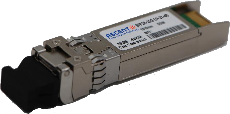
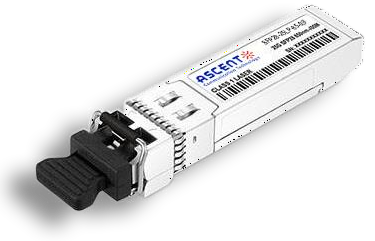
25G SFP28 1310 nm 40km
Ascentãs SFP28 transceivers are designed for use in 25G Gigabit Ethernet links with distances up to 40 km over single-mode fiber. These transceivers include an high sensitivity APD photo detector diode and DFB transmitter. Digital diagnostic functions are available via a 2-wire interface. Ascentãs SFP28 transceivers provide a unique enhanced digital diagnostic monitoring interface which allows real-time access to device operating parameters such as transceiver temperature, laser bias current, transmitted optical power, received optical power, and transceiver supply voltage. It also defines a sophisticated system of alarm and warning flags which alerts end users when particular operating parameters are outside of a factory set normal range. Ascentãs 25G SFP28 transceivers are compliant with SFF 8431 and SFF 8472 standards, and offer a convenient solution for high-speed storage area networks, OBSAI and CPRI 10 applications, and LTE optical repeater applications.
ôñ Operating data rate up to 25.78Gbps
ôñ Rate Adaptation
ôñ Up to 40km transmission distance
ôñ High sensitivity APD photodiode and TIA
ôñ LC single connector
ôñ Hot pluggable 20pin connector
ôñ Low power consumption
ôñ Single +3.3V ôÝ5% power supply
ôñ Compliant with SFF-8472 & IEEE 802.3cc
ôñ Fully RoHS Compliant
ôñ Operating Temperature Range:
Commercialÿ¥0ô¯C to +70ô¯C
Industrial: -40ô¯C to +85ô¯C
Absolute Maximum Ratings
Parameter | Symbol | Min. | Typ. | Max. | Unit |
Storage Temperature | Ts | -40 | 85 | ô¯C | |
Relative Humidity | RH | 5 | 95 | % |
Recommended Operating Conditions
Parameter | Symbol | Min. | Typ. | Max. | Unit | Notes
|
Case Temperature | Tc | 0 | 70 | ô¯C | 1 | |
-40 | 85 | 2 | ||||
Power Supply Voltage | VCC | 3.14 | 3.30 | 3.46 | V | |
Bit Rate | BR | 25.78125 | Gbps | |||
Bit Error Ratio | BER | 5*10-5 | ||||
Max Supported Link Length | L | 80 | km | Over SMF |
Note1, 2: See order information
Optical Characteristics
Parameter Transmitter | Symbol
| Min.
| Typ.
| Max.
| Unit | Note |
Center Wavelength | ö£ | 1290 | 1330 | nm | ||
Side-mode Suppression Ratio | SMSR | 30 | dB | |||
Average Optical Power | Pavg | -2 | 6.0 | dBm | ||
Optical Modulation Amplitude | TxOMA | 0 | dBm | |||
Transmitter and Dispersion Penalty | TDP | 2.7 | dB | |||
Average Launch Power of OFF Transmitter | Poff | -20 | dBm | |||
Extinction Ratio | ER | 4 | - | dB | ||
Optical Return Loss Tolerance | - | 20 | dB | |||
Transmitter Reflectance | -26 | dB | ||||
Receiver | ||||||
Center Wavelength | ö£c | 1290 | - | 1330 | nm | |
Damage Threshold | -3 | dBm | ||||
Receive Power Overload | -5 | dBm | ||||
Receiver Reflectance | -26 | dB | ||||
Receiver Sensitivity | S | -19 | dBm | 1 | ||
LOS Assert | LOSA | -30 | - | dBm | ||
LOS De-assert | LOSD | - | - | -21 | dBm | |
LOS Hysteresis | 0.5 | dB |
Note:
1. Measured at 25.78Gb/s, ER>4dBm, PRBS 2 31 -1 and BER better than or equal to 5E-5.
Electric Ports Definition
Parameter | Symbol | Min. | Typ. | Max. | Unit | Notes |
Transmitter | ||||||
Input Differential Impedance | RIN | 100 | öˋ | |||
Single-ended Data Input Swing | VIN | 90 | 450 | mVp-p | ||
Transmit Disable Voltage | VDIS | 2 | VCCHOST | V | ||
Transmit Enable Voltage | VEN | VEE | VEE+0.8 | V | ||
Transmit Fault Assert Voltage | VFA | 2 | VCCHOST | V | ||
Transmit Fault De-Assert Voltage | VFDA | VEE | VEE+0.4 | V | ||
Receiver | ||||||
Single-ended Data Output Swing | VOD | 200 | 450 | mVp-p | ||
LOS Fault | VLOSFT | 2 | VCCHOST | V | ||
LOS Normal | VLOSNR | VEE | VEE+0.4 | V | ||
Digital Diagnostics
Parameter | Accuracy | Unit |
Internally measured transceiver temperature | +/-3 | ô¯C |
Internally measured transceiver supply voltage | +/-3 | % |
Measured Tx bias current | +/-10 | % |
Measured Tx output power | +/-3 | dB |
Measured Rx received average optical power | +/-3 | dB |


64G SFP56 850nm 100m
64 Gb/s SFP56 SW Fibre Channel 850nm Transceiver
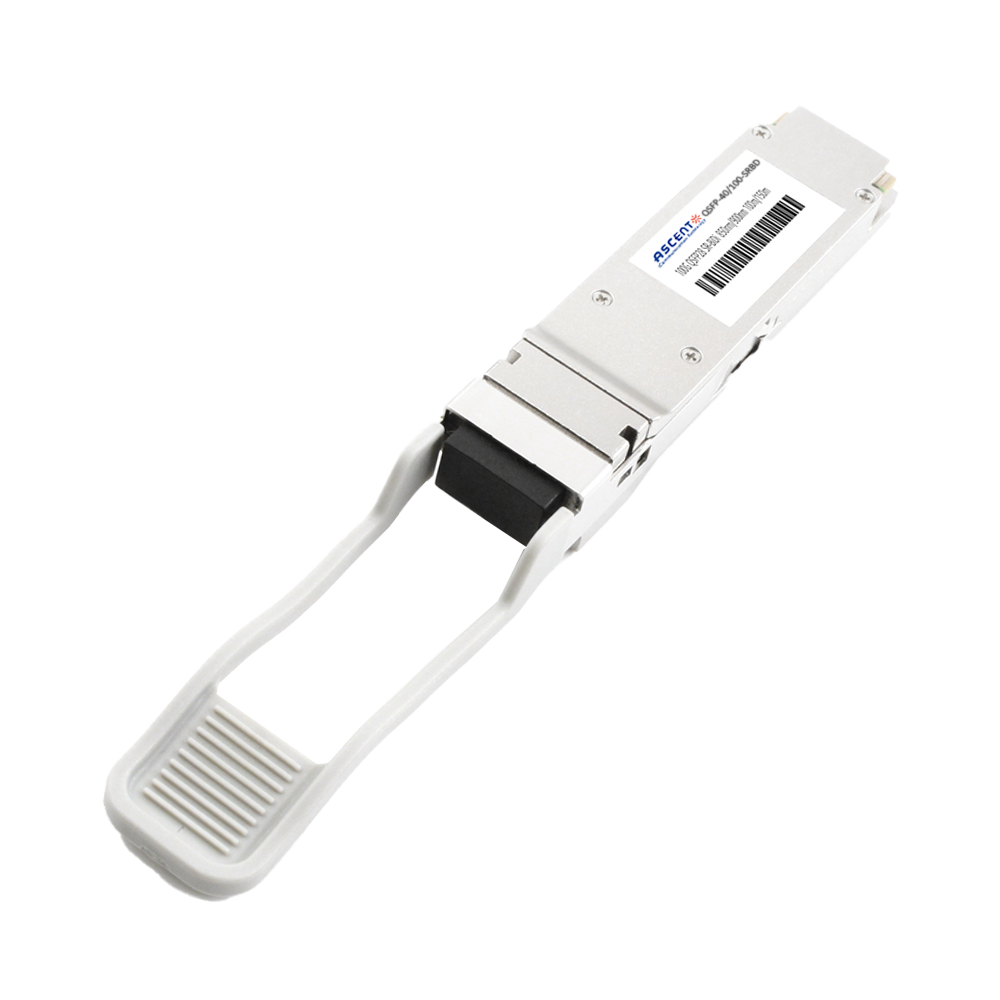
40/100G SFP28 SWDM4 100m
40/100Gb/s QSFP28, Bi-Di, Duplex LC 100m Transceiver

40G QSFP+ ER4 Industrial 40 km
40 Gb/s QSFP+ ER4 40 km Transceiver

40G QSFP+ ER4 40 km
40 Gb/s QSFP+ ER4 40 km Transceiver

40G QSFP+ LR4 Industrial 10 km
40 Gb/s QSFP+ LR4 10 km Transceiver

40G QSFP+ LR4 10 km
QSFP-AQ-LP-W4-10 40 Gb/s QSFP LR4 10 km Transceiver

40G QSFP+ PSM4 2 km
40 Gb/s QSFP+ PSM4 Transceiver 2km
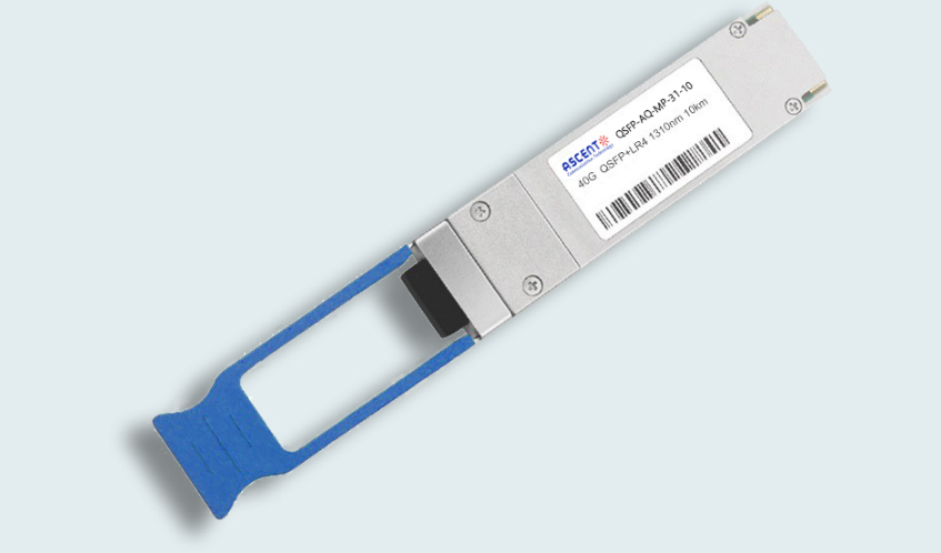
40G QSFP+ PLR4 1310 nm 10 km
QSFP-AQ-MP-31-10 40 Gb/s QSFP+ PSM 1310nm 10km MPO Optical Transceiver
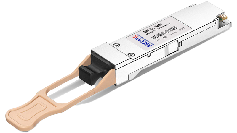
40G QSFP+ CSR4 300m
40 Gb/s 300m QSFP+ CSR4 Transceiver
40GBASE-UNIV QSFP+ MMF and SMF
40G QSFP+ UNIV MMF/SMF 150m/2km
40G QSFP+ CWDM 2 km
40G QSFP+ CWDM 2 km
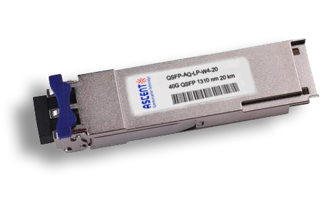
40G QSFP CWDM 20 km
QSFP-AQ-LP-W4-20 40 Gb/s QSFP CWDM 20 km Transceiver
40G QSFP+ SR4 300 m
40 Gb/s QSFP+ SR4 Transceiver with DDM

40G QSFP+ BIDI 150m
40 Gb/s QSFP+ BiDi Transceiver 150m
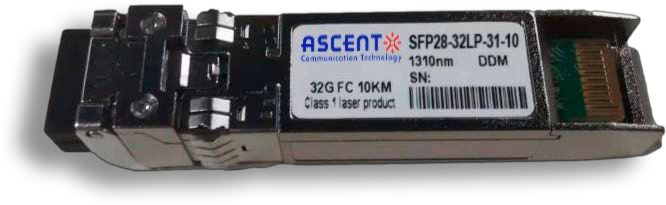
32G SFP28 1310 nm 10 km
32G FC 1310 nm 10 km SFP28 Transceiver

32G SFP28 SR 850 nm 100 m
SFP28-32LP-85-01 32GBASE-SR SFP28 850 nm 100 m DOM Transceiver
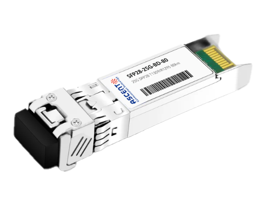
25G SFP28 BIDI 80 km
25G SFP28 BIDI 80 km Transceiver
.png)
25G SFP28 CWDM 10 km(E)
25 Gb/s CWDM EML SFP28 10 km Transceiver
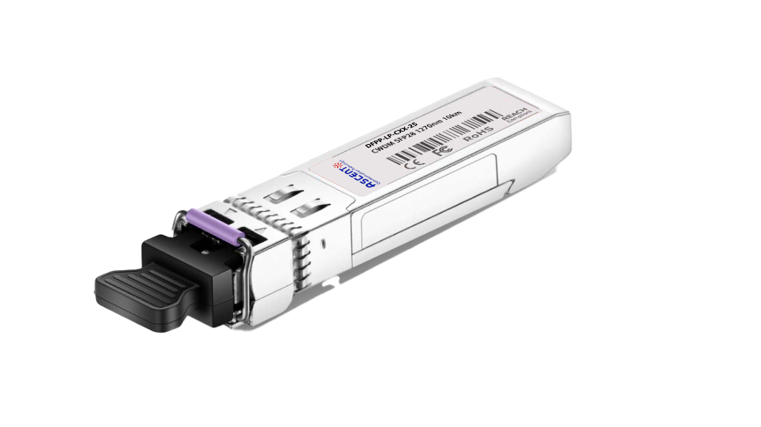
25G SFP28 CWDM 10 km(D)
25 Gb/s CWDM SFP28 10 km Transceiver

25G SFP28 ZR 1310nm 80km
25 Gbps 1310 nm 80 km SFP28 ZR Transceiver
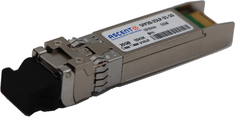
25G SFP28 1310 nm 10 km
SFP28-25LP-31-10 25 Gb/s 1310 nm Single-Mode SFP+ Transceiver
25G SFP28 850 nm 300m
25 Gb/s 850 nm Multi-Mode SFP28 300m Transceiver

25G SFP28 850 nm 100m
SFP28-25LP-85-01 28 Gb/s 850 nm Multi-Mode SFP28 Transceiver

10/25G SFP28 1310nm 40km
10/25 Gb/s SFP28 1310 nm 40km Transceiver

10/25G SFP28 1310nm 10km
10/25 Gb/s SFP28 1310 nm 10km DDM Transceiver

10/25G SFP28 850 nm 300m
10/25 Gb/s SFP28 850 nm 300m Transceiver

10/25G SFP28 850 nm 100m
10/25 Gb/s SFP28 850 nm 100m Transceiver
White Paper
Press Releases
Briefings 1
Briefings 2
Videos, etc.
QRG
Manual1
Manual2
Get in touch with our experts
Feedback