- FTTH ã 10G XGSPON >SFP Transceivers >2.5G SFP BiDi 10 km
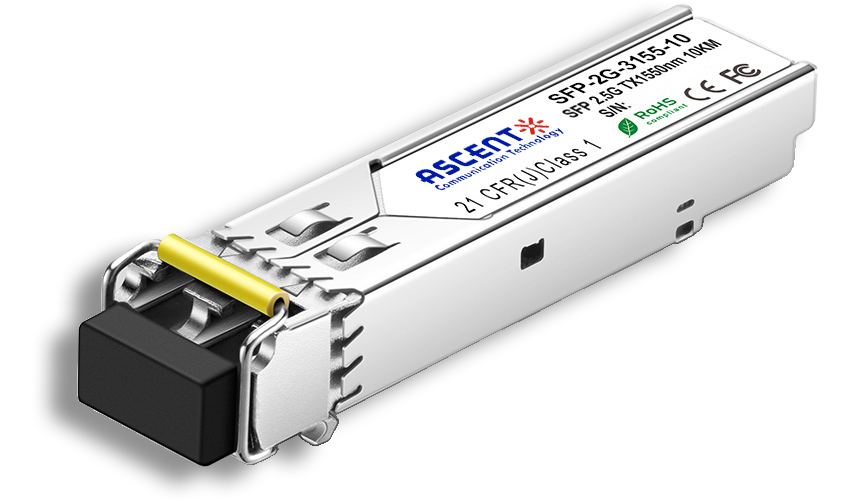
2.5G SFP BiDi 10 km
ASCENT 2.5G 10 km BiDi Small Form Factor Pluggable (SFP) transceiver modules are compatible with the Small Form Factor Pluggable Multi-Sourcing Agreement (MSA).
ã Operating data rate up to 2.5 Gbps
ã 1310 nm and 1550 nm operating wavelength
ã PIN-TIA receiver
ã 20 km with 9/125 ôçm SMF
ã Single 3.3V power supply
ã Hot-pluggable SFP footprint
ã LC connector interface
ã Power dissipation < 1.0 W
ã Operating temperature: 0 ô¯C to +70 ô¯C
ã Compliant with SFF-8472
ã Compliant with MSA SFP specification
ã Class 1 FDA and IEC60825-1 laser safety compliant
Parameter | Symbol | Min. | Max. | Unit |
Storage Temperature | Ts | ã40 | +85 | ô¯C |
Maximum Supply Voltage | Vcc | ã0.5 | 3.6 | V |
Operating Relative Humidity | RH | 5 | 85 | % |
Note: Exceeding any one of these values may destroy the device immediately.
Recommended Operating Conditions
Parameter | Symbol | Min. | Typ. | Max. | Unit | |
Operating Case Temperature | Tc | 0 | 70 | ô¯C | ||
Power Supply Voltage | Vcc | 3.15 | 3.3 | 3.47 | V | |
Power Supply Current | Icc | 300 | mA | |||
Data Rate | FC | 1.063 | Gbps | |||
2XFC | 2.125 | |||||
OCã48/STMã16 | 2.5 | |||||
Optical Characteristics
Parameter | Symbol | Min. | Typ. | Max. | Unit | |
9 ôçm Core Diameter MMF | L | 20 | km | |||
Data Rate | 2.488 | Gbps | ||||
Transmitter | ||||||
Center Wavelength | SFPã2Gã3155ã10 | ö£C | 1290 | 1310 | 1330 | nm |
SFPã2Gã5531ã10 | ö£C | 1530 | 1550 | 1570 | nm | |
Spectral Width (ã20 dB) | ãö£ | 1 | nm | |||
Side Mode Suppression Ratio | SMSR | 30 | dB | |||
Average Output Power1 | Pout | ã5 | 0 | dBm | ||
Extinction Ratio | ER | 8.2 | dB | |||
Rise/Fall Time (20 % to 80 %) | tr/tf | 0.16 | ns | |||
Output Optical Eye2 | Compliant with IEEE 802.3 | |||||
Pout@TX Disable Asserted | Pout | ã45 | dBm | |||
Receiver | ||||||
Center Wavelength | SFPã2Gã3155ã10 | ö£C | 1530 | 1550 | 1570 | nm |
SFPã2Gã5531ã10 | ö£C | 1290 | 1310 | 1330 | nm | |
Receiver Sensitivity*(Note3) | Pmin | ã18 | dBm | |||
Receiver Overload | Pmax | ã3 | dBm | |||
LOS DeãAssert | LOSD | ã19 | dBm | |||
LOS Assert | LOSA | ã30 | dBm | |||
LOS Hysteresis | 0.5 | dB | ||||
Notes:
1. Output is coupled into a 9/125 ôçm SMF.
2. Filtered, measured with a PRBS 223 ã 1 test pattern @ 2.5 Gbps.
3. Minimum average optical power, measured at BER less than 1Eã12, with 223ã1 PRBS and ER = 8.2 dB.
Electrical Characteristics
Parameter | Symbol | Min. | Typ. | Max. | Unit | Notes | |
Transmitter | |||||||
LVPECL Inputs (Differential) | Vin | 400 | 2000 | mVpp | AC Coupled Inputs1 | ||
Input Impedance (Differential) | Zin | 85 | 100 | 115 | öˋ | Rin > 100 köˋ @ DC | |
TX_Dis | Disable | 2 | Vcc+0.3 | V | |||
Enable | 0 | 0.8 | |||||
TX_FAULT | Fault | 2 | Vcc+0.3 | V | |||
Normal | 0 | 0.8 | |||||
Receiver | |||||||
LVPECL Outputs (Differential) | Vout | 400 | 2000 | mVpp | AC Coupled Outputs1 | ||
Output Impedance (Differential) | Zout | 85 | 100 | 115 | öˋ | ||
TX_Disable Assert Time | t_off | 10 | ôçs | ||||
RX_LOS | LOS | 2 | Vcc+0.3 | V | |||
Normal | 0 | 0.8 | |||||
MOD_DEF (0.2) | VoH | 2.5 | Vcc+0.3 | V | With Serial ID | ||
VoL | 0 | 0.5 | |||||
Notes:
1. LVPECL logic, internally AC coupled.
Digital Diagnostic Functions
Parameter | Range | Unit | Accuracy | Calibration |
Temperature | 0 to 70 | ô¯C | ôÝ3 ô¯C | Internal / External |
Voltage | 3.0 to 3.6 | V | ôÝ3 % | Internal / External |
Bias Current | 10 to 80 | mA | ôÝ10 % | Internal / External |
TX Power | ã5 to 0 | dBm | ôÝ3 dB | Internal / External |
RX Power | ã18 to ã3 | dBm | ôÝ3 dB | Internal / External |
Note: The transceivers provide serial ID memory contents and diagnostic information about the present operating conditions by the 2ãwire serial interface (SCL, SDA). The diagnostic information with internal calibration or external calibration all are implemented, including received power monitoring, transmitted power monitoring, bias current monitoring, supply voltage monitoring and temperature monitoring.

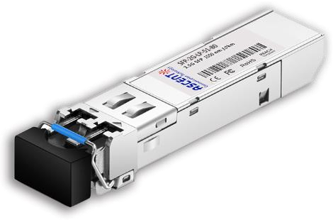
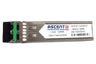
2.5G SFP 1550nm 80km
SFP 1550nm 2.5Gbps 80km Transceiver
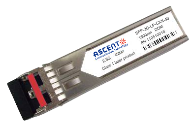
2.5G SFP CWDM 40 km
SFP-2G-LP-CXX-40 2.5 Gbps CWDM Single-mode SFP Transceiver

2.5G SFP 1310nm 20km
SFP 1310nm 2.5Gbps LX 20km Transceiver

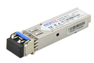
2.5G SFP 1310nm 10km
2.5 Gb/s 1310nm Single-mode SFP Transceiver
2.5G SFP 1310 nm 2 km
SFP-2G-LP-31-2K 2.5 Gb/s 1310 nm Single-mode SFP Transceiver
1.25G SFP EZX 1550 nm 120 km
SFP-AGLP-51-120 1.25Gb/s 1550nm Single-mode SFP Transceiver
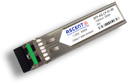
1.25G SFP ZX 1550 nm 80 km
SFP-AG-LP-51-80 1.25 Gb/s 1550 nm Single-Mode SFP Transceiver
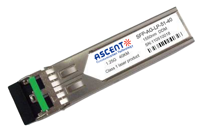
1.25G SFP EX 1550 nm 40 km
SFP-AG-LP-51-40 1.25 Gbps 1550 nm Single-mode SFP Transceiver
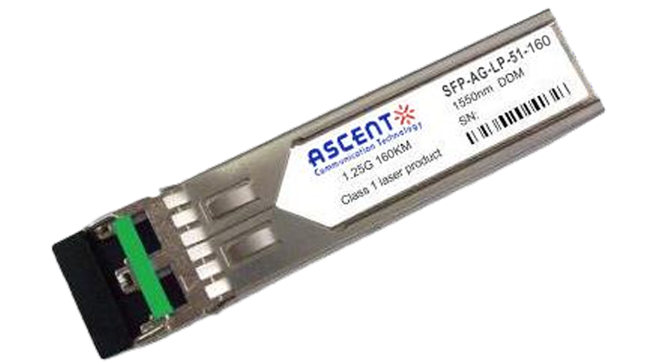
1.25G SFP 1550 nm 160 km
1.25 Gb/s SFP 1550nm 160km Transceiver
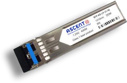
1.25G SFP EX 1310 nm 40 km
SFP-AG-LP-31-40 1.25 Gb/s 1310 nm Single-mode SFP Transceiver
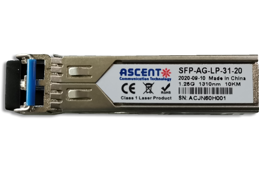
1.25G SFP 1310 nm 20 km
SFPP-AG-LP-31-20 1.25 Gb/s 1310 nm Single-Mode SFP Transceiver
1.25G SFP 1310 nm 10 km
SFPP-AG-LP-31-10 1.25 Gb/s 1310 nm Single-Mode SFP Transceiver

1.25G SFP SR 850 nm 550 m
SFP-AG-LP-85-05 1.25Gb/s 850 nm Multi-Mode SFP Transceiver
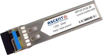
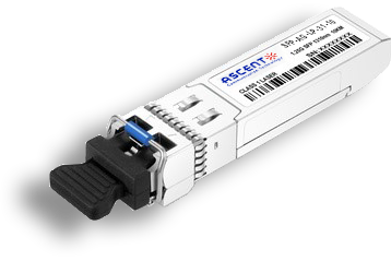
1.25G SFP BX 3155 20 km
SFP BIDI 1.25G 1310/1550 nm 20 km DDM

1.25G SFP BX 3155 3 km
SFP BIDI 1.25G 1310/1550 nm 3 km

1.25G SFP BX 4950 120 km
SFP-AGLP4955-120 SFP BIDI 1.25G 1490/1550 nm 120 km DDM
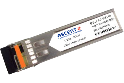
1.25G SFP BX 4950 80 km
SFP-AGLP-4955-80 SFP BIDI 1.25G 1490/1550 nm 80 km DDM
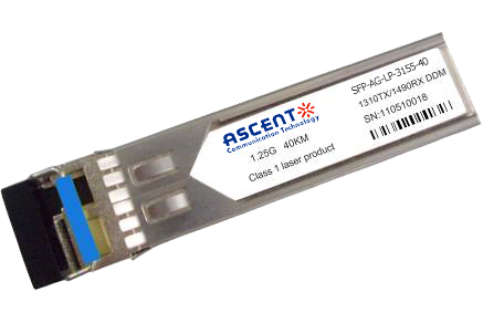
1.25G SFP BX 3150 40 km
SFP-AGLP-3155-40 SFP BIDI 1.25G 1310/1550 nm 40 km DDM

1.25G SFP BX 3149 20 km
SFP-AGLP-3149-20 SFP BIDI 1.25G 1310/1490 nm 20 km DDM
1.25G SFP CWDM 4931 20 km
SFP-AGSP-4931-20 SFP Plug-in, 1.25Gbps, 20km, BIDI, TX=1490nm, RX=1310nm, SC/PC Blue
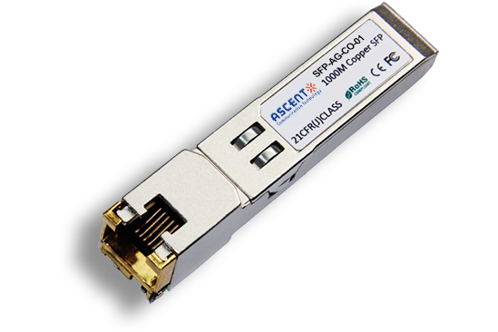
1000M Copper SFP
SFP-AG-CO-01 1000M Copper SFP Transceiver

10/100/1000M Copper SFP
SFP-AG-CO-02 10/100/1000M Copper SFP Transceiver

1000M Copper SFP w/ Auto-Negotiation
SFP-AG-CO-03 1000M Auto Adapt Copper SFP Transceiver
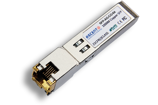
10/100/1000M Copper SFP w/ Link Indicator
SFP-AG-CO-04 10/100/1000M Copper SFP Transceiver w/ Link Indicator
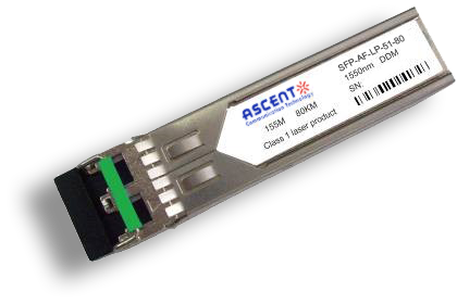
155M SFP 1550 nm 80 km
SFP-AF-LP-51-80 155 Mb/s 1550ô nm Single?Mode SFP Transceiver
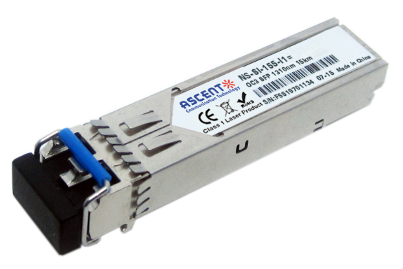
155M SFP OC3 1310nm 15 km
SFP_ONS-SI-155-I1 SFP Plug-in, OC3 155Mbps 1310nm Single-mode SFP Optical Transceiver, 15km, LC
White Paper
Press Releases
Briefings 1
Briefings 2
Videos, etc.
QRG
Manual1
Manual2
Get in touch with our experts
Feedback