- FTTH ã 10G XGSPON >SFP Transceivers >2.5G SFP 1550nm 80km
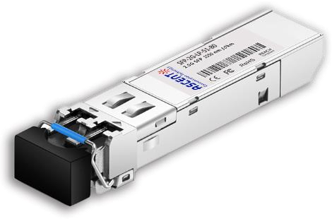
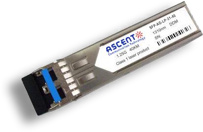
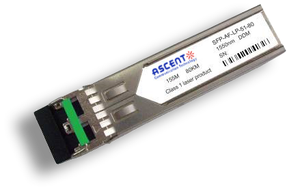
2.5G SFP 1550nm 80km
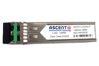
The SFP 2.5Gb/s 1550nm transceiver is a high-performance optical module designed for long-reach transmission up to 80 km over single-mode fiber (SMF). Supporting data rates up to 2.5 Gb/s, it is well suited for telecom and enterprise applications including SONET OC-48 / SDH STM-16 and Fiber Channel links. Its compact, hot-pluggable SFP form factor enables easy integration into a wide range of networking equipment. The module incorporates a 1550 nm DFB laser transmitter and a high-sensitivity Super TIA receiver, ensuring stable optical performance and extended transmission distance. The optical interface uses a duplex LC connector, while the electrical interface supports a standard SFP connection with a single +3.3V power supply. With low power consumption typically below 1.5W, the transceiver provides an efficient solution for long-distance optical communication. Compliant with SFF-8472 digital diagnostic monitoring (DDM), the module allows real-time access to critical operating parameters such as temperature, voltage, and optical power. Designed for reliable operation in demanding environments, it supports both commercial (0ô¯C to 70ô¯C) and industrial (-40ô¯C to 85ô¯C) temperature ranges, and is fully RoHS compliant and lead-free, making it suitable for a wide range of carrier and industrial network deployments.
ôñ Up to 2.5Gb/s Data Links
ôñ Hot-Pluggable
ôñ 1550nm DFB laser transmitter
ôñ Super Tia receiver
ôñ Duplex LC connector
ôñ Up to 80km on 9/125pm SMF
ôñ Single +3.3V Power Supply
ôñ Monitoring Interface Compliant with SFF-8472
ôñ Low power consumption<1.5W typically
ôñ Operating temperature range:
Commercial: 0ô¯C to 70ô¯C
Industrial: -40ô¯C to 85ô¯C
ôñ RoHS compliant and Lead Free
Absolute Maximum Ratings
Parameter | Symbol | Min. | Max. | Unit |
Storage Temperature | Ts | -40 | +85 | ô¯C |
Maximum Supply Voltage | Vcc | -0.5 | 4.0 | V |
Operating Relative Humidity | RH | 0 | 85 | % |
Parameter Operating Case Temperature | Symbol Tc | Min. 0 | Typ.
| Max. +70 | Unit ô¯C | Note SFP-2G-LP-51-80 |
-40 | +85 | ô¯C | SFP-2G-LP-51-80A |
Optical Characteristics
Parameter | Symbol | Min. | Typ. | Max. | Unit | Note |
Transmitter | ||||||
Center Wavelength | ö£c | 1530 | 1550 | 1570 | nm | 1 |
Spectral Width(-20dB) | ü | 1 | nm | |||
Side Mode Suppression Ratio | SMSR | dB | ||||
Optical Output Power | Pout | 0 | 5 | dBm | 2 | |
Optical Rise/Fall Time | tr / tf | 260 | ps | 3 | ||
Extinction Ratio | ER | 9 | dB | |||
Deterministic Jitter Contribution | TXADJ | 56.5 | ps | 4 | ||
Total Jitter Contribution | TXATJ | 119 | ps | 4 | ||
Eye Mask for Optical Output | Compliant with IEEE802.3z (class 1 laser safety) | |||||
Receiver | ||||||
Optical Input Wavelength | 1530 | 1570 | nm | |||
Optical Input Power | Pin | -28 | -1 | dBm | 5,6 | |
Receiver Overload | Pol | -3 | dBm | 5,6 | ||
RX Sensitivity | Sen | -28 | dBm | 5,6 | ||
Receiver Reflectance | 12 | dB | ||||
RX_LOS Assert | LOSA | -42 | dBm | |||
RX_LOS Deassert | LOSD | -29 | dBm | |||
RX_LOS Hysteresis | LOSH | 2 | 2.5 | dB | ||
General Characteristics | ||||||
Data Rate | BR | 2125 | 2500 | Mb/s | ||
Bit Error Rate | BER | 10-12 | ||||
Max. Supported Link Length on 9/125pm SMF@2.5G | LMAX | 80 | km | 7,8 | ||
Total System Budget | LB | 26 | dB | 7,8 | ||
Note:
1. Also specified to meet curves in FC-PI 13.0 Figures 18 and 19, which allow trade-off between wavelength spectral widths.
2. Class 1 Laser Safety per FDA/CDRH and EN (IEC) 60825 regulations.
3. Unfiltered, 20-80%. Complies with IEEE 802.3 (Gig. E), FC 1x and 2x eye masks when filtered.
4. Measured with DJ-free data input signal. In actual application, output DJ will be the sum of input DJ and . DJ.
5. Measured with conformance signals defined in FC-PI 13.0 specifications.
6. Measured with PRBS 223-1 at 10-12 BER.
7. Dispersion limited per FC-PI Rev. 13.
8. Attenuation of 0.25dB/km is used for the link length calculations. Distances are indicative only. Please refer to the Optical Specifications in Table IV to calculate a more accurate link budget based on specific
conditions in your application.
Electrical Characteristics (Top = Tc, Vcc = 3.135 to 3.465 Volts)
Parameter | Symbol | Min. | Typ. | Max. | Unit | Note |
Supply Voltage | Vcc | 3.14 | 3.30 | 3.47 | V | |
Supply Current | Icc | 300 | mA | |||
Inrush Current | Isurge | Icc+30 | mA | |||
Maximum Power | Pmax | 1.0 | W | |||
Transmitter | ||||||
Input Differential Impedance | Rin | 90 | 100 | 110 | ||
Single Ended Data Input Swing | Vin PP | 200 | 1200 | mVp-p | ||
Transmit Disable Voltage | VD | Vcc-1.3 | Vcc | V | 1 | |
Transmit Enable Voltage | VEN | Vee | Vee+0.8 | V | ||
Transmit Disable Assert Time | Tdessert | 10 | us | |||
Receiver | ||||||
Single Ended Data Output Swing | Vout,pp | 300 | 1000 | mv | 2 | |
Data Output Rise Time | tr | 260 | ps | |||
Data Output Fall Time | tf | 260 | ps | |||
LOS Fault | Vlosfault | Vcc-0.5 | VCC_host | V | 3 | |
LOS Normal | Vlos norm | Vee | Vee+0.5 | V | 3 | |
Power Supply Rejection | PSR | 100 | mVpp | |||
Deterministic Jitter Contribution | RXADJ | 51.7 | ps | |||
Total Jitter Contribution | RXATJ | 122.4 | ps | |||
Note:
1. Or open circuit.
2. Into 100 ohm differential termination.
3. LOS is LVTTL. Logic 0 indicates normal operation; logic 1 indicates no signal detected.

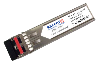
2.5G SFP CWDM 40 km
SFP-2G-LP-CXX-40 2.5 Gbps CWDM Single-mode SFP Transceiver
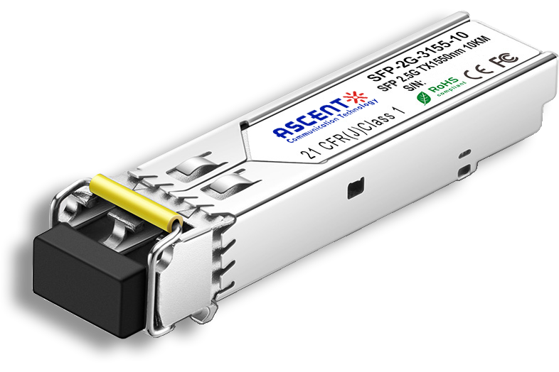
2.5G SFP BiDi 10 km
SFP-2G-LP-3155-10 2.5 Gb/s BiDi Single-mode SFP Transceiver

2.5G SFP 1310nm 20km
SFP 1310nm 2.5Gbps LX 20km Transceiver

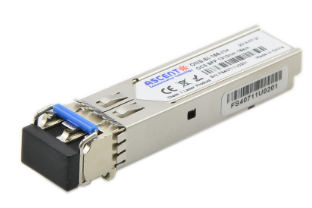
2.5G SFP 1310nm 10km
2.5 Gb/s 1310nm Single-mode SFP Transceiver
2.5G SFP 1310 nm 2 km
SFP-2G-LP-31-2K 2.5 Gb/s 1310 nm Single-mode SFP Transceiver
1.25G SFP EZX 1550 nm 120 km
SFP-AGLP-51-120 1.25Gb/s 1550nm Single-mode SFP Transceiver
1.25G SFP ZX 1550 nm 80 km
SFP-AG-LP-51-80 1.25 Gb/s 1550 nm Single-Mode SFP Transceiver
1.25G SFP EX 1550 nm 40 km
SFP-AG-LP-51-40 1.25 Gbps 1550 nm Single-mode SFP Transceiver
1.25G SFP 1550 nm 160 km
1.25 Gb/s SFP 1550nm 160km Transceiver
1.25G SFP EX 1310 nm 40 km
SFP-AG-LP-31-40 1.25 Gb/s 1310 nm Single-mode SFP Transceiver
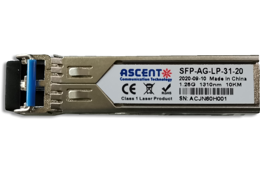
1.25G SFP 1310 nm 20 km
SFPP-AG-LP-31-20 1.25 Gb/s 1310 nm Single-Mode SFP Transceiver
1.25G SFP 1310 nm 10 km
SFPP-AG-LP-31-10 1.25 Gb/s 1310 nm Single-Mode SFP Transceiver

1.25G SFP SR 850 nm 550 m
SFP-AG-LP-85-05 1.25Gb/s 850 nm Multi-Mode SFP Transceiver
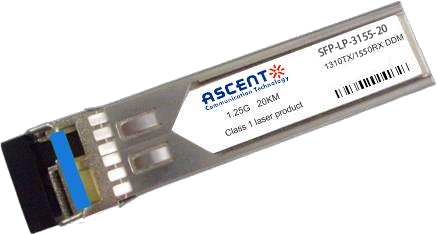
1.25G SFP BX 3155 20 km
SFP BIDI 1.25G 1310/1550 nm 20 km DDM

1.25G SFP BX 3155 3 km
SFP BIDI 1.25G 1310/1550 nm 3 km

1.25G SFP BX 4950 120 km
SFP-AGLP4955-120 SFP BIDI 1.25G 1490/1550 nm 120 km DDM
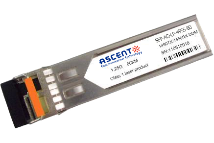
1.25G SFP BX 4950 80 km
SFP-AGLP-4955-80 SFP BIDI 1.25G 1490/1550 nm 80 km DDM
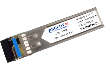
1.25G SFP BX 3150 40 km
SFP-AGLP-3155-40 SFP BIDI 1.25G 1310/1550 nm 40 km DDM

1.25G SFP BX 3149 20 km
SFP-AGLP-3149-20 SFP BIDI 1.25G 1310/1490 nm 20 km DDM
1.25G SFP CWDM 4931 20 km
SFP-AGSP-4931-20 SFP Plug-in, 1.25Gbps, 20km, BIDI, TX=1490nm, RX=1310nm, SC/PC Blue
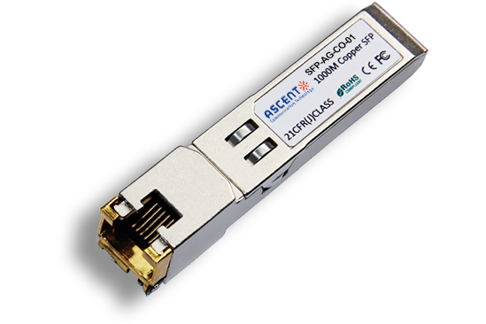
1000M Copper SFP
SFP-AG-CO-01 1000M Copper SFP Transceiver

10/100/1000M Copper SFP
SFP-AG-CO-02 10/100/1000M Copper SFP Transceiver

1000M Copper SFP w/ Auto-Negotiation
SFP-AG-CO-03 1000M Auto Adapt Copper SFP Transceiver
10/100/1000M Copper SFP w/ Link Indicator
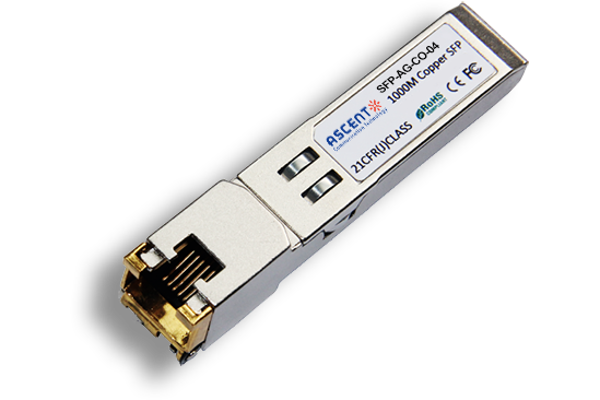
SFP-AG-CO-04 10/100/1000M Copper SFP Transceiver w/ Link Indicator
155M SFP 1550 nm 80 km
SFP-AF-LP-51-80 155 Mb/s 1550ô nm Single?Mode SFP Transceiver
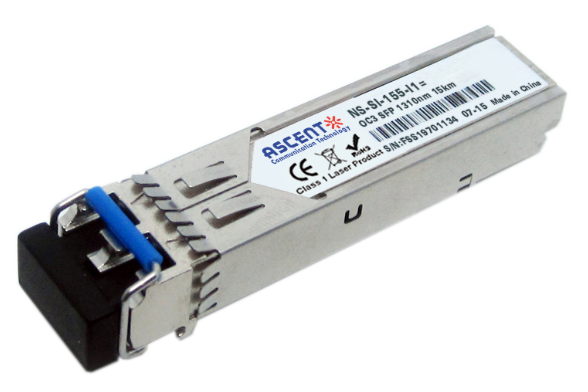
155M SFP OC3 1310nm 15 km
SFP_ONS-SI-155-I1 SFP Plug-in, OC3 155Mbps 1310nm Single-mode SFP Optical Transceiver, 15km, LC
White Paper
Press Releases
Briefings 1
Briefings 2
Videos, etc.
Manual1
Manual2
Get in touch with our experts
Feedback