- FIBER OPTIC TRANSCEIVERS >Optical Cables and Accessories >800G QSFP Q112 AEC Cable
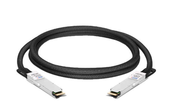
800G QSFP Q112 AEC Cable
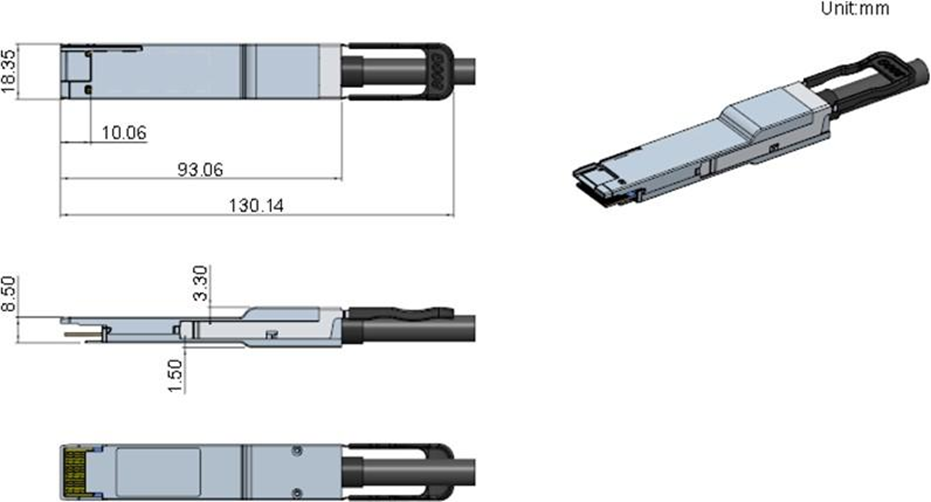
Ascent's 800G QSFP-DD to QSFP-DD Active Electrical Cable (AEC) is a high-performance, low-latency copper interconnect solution designed for next-generation AI infrastructure, cloud data centers, high-performance computing (HPC), and hyperscale Ethernet networks. The cable integrates advanced DSP retimer technology to extend copper transmission distance while maintaining excellent signal integrity, enabling reliable 800Gb/s connectivity between servers, switches, storage systems, and GPU clusters. The AEC features QSFP-DD connectors on both ends and supports an aggregate data rate of 800Gb/s (8 × 106.25Gb/s PAM4) over a single cable assembly. Integrated signal conditioning and retiming technology compensate for channel loss, improve eye margin, and ensure robust transmission performance over longer copper links compared with passive DAC solutions. Operating from a 3.3V power supply, the cable supports hot-pluggable operation and provides comprehensive diagnostics, including PRBS generation and checking, loopback testing, signal-to-noise ratio (SNR) monitoring, eye histogram analysis, and advanced performance monitoring for simplified deployment and maintenance. Designed in accordance with the QSFP-DD MSA and CMIS 5.0 specifications, the Ascent 800G AEC delivers a compact, energy-efficient, and cost-effective interconnect solution for high-density networking environments. The cable supports 800G Ethernet applications and is backward compatible with 400G and 200G operating modes, making it an ideal choice for AI clusters, Ethernet switches, storage networks, and next-generation data center architectures requiring reliable medium-reach electrical interconnects.
· QSFP-DD to QSFP-DD 800G Application
· 3.3V Power Supply
· Hot Pluggable
· Host and line interface support loopbacks and PRBS generator/checker for diagnostic operations
· Performance monitor in features including SNR, eye histogram and more
· Comprehensive test and debug capabilities
· RoHS Compliance
· BER<10-8(Pre FEC)*
· BER<10-15(Post FEC)*
* Tested with QPRBS31 pattern
Parameter | Symbol | Min. | Typ. | Max. | Unit | Note |
Storage Temperature | Tstg | -40 | - | +85 | °C | |
Supply Voltage | Vcc | -0.3 | - | 3.6 | V | |
Relative Humidity | RH | 10% | - | 85% | % | Non-Condensing |
Recommended Operating Conditions
Parameter | Symbol | Min. | Typ. | Max. | Unit | Note |
Operating Case Temperature | TCASE | 0 | - | +70 | °C | |
Power Supply Voltage | VCC | 3.13 | 3.3 | 3.465 | V | |
Power Consumption | PDISS | - | - | W | ||
Operating Relative Humidity | 0 | 85 | % |
General Product Characteristics
Parameter | Description | |
P1 End | P2 End | |
Module Form Factor | QSFP-DD800 | QSFP-DD800 |
Full/Half Active Full | Full Active | |
Default Data Rate | 800G(8*112G-PAM4) to 800G(8*112G-PAM4) | |
Number of Data Lanes /Data Rate | 8Lane(16Pair)/112G PAM4 | |
Cable Construction | Expando over discrete twinax and metal braid | |
Module DSP Mode (Host to Line Side) | Retimer 8*10G to 8*100G | Retimer 8*100G to 8*100G |
DSP Model | Marvell Lynx800 | Marvell Lynx800 |
Management Interface | CMIS 5.0 | CMIS 5.0 |
Nominal Data Rate per Lane | 106.25Gbps(PAM4), KP4 FEC must be enabled | 106.25Gbps(PAM4), KP4 FEC must be enabled |
Pre-FEC Bit Ratio (Test with PRBS31 Patent) | <1e-8 | <1e-8 |
Post-FEC Bit Ratio | <1e-15 | <1e-15 |
Power Consumption per End | 11W | 11W |
Host Max I2C Interface | 400kbps | |
Time to CMIS Ready | 100milliseconds | |
Time to Link | 15seconds | |
Hot Swappable/Pluggable | Yes | |
Data Rate Capabilities | 800G: 112G PAM4 (data rate=106.25Gbps) 400G: 56G PAM4 (data rate=53.125Gbps) 200G: 25G NRZ (data rate=25.78125Gbps) | |
Electrical Characteristics
Parameter | Min. | Typ. | Max. | Unit | Note | |
Characteristic Impedance | 90 | 100 | 110 | ohm | ||
Time Propagation Delay (Informative) | 4.9 | ns | ||||
Low Speed Electrical Signal
Parameter | Symbol | Min. | Max. | Unit | Note |
Module Output SCL and SDA | VOL | 0 | 0.4 | V | IOL(max)=3.0mA for fast mode,20mA for Fast-mode plus |
VOH | VCC-0.5 | VCC+0.3 | V | ||
Module Input SCL and SDA | VOL | -0.3 | Vcc*0.3 | V | |
VOH | VCC*0.7 | Vcc +0.5 | V | ||
Capacitance for SCL and SDA I/O Pin | Ci | 14 | pF | ||
Total Bus Capacitive Load for SCL and SDA | Cb | 100 | pF | 3.0k Ohms Pull up resistor, max | |
200 | pF | 1.6k Ohms Pull up resistor, max | |||
LPMode/TxDis,Reset and ModeSeIL | VIL | -0.3 | 0.8 | V | |Iin| |
VIH | 2 | VCC+0.3 | V | ||
IntL/RxLOS | VOL | 0 | 0.4 | V | IOL=2.0mA |
VOH | VCC-0.5 | VCC+0.3 | V | 10k ohms pull-up to Host Vcc | |
ModPrsL | VOL | 0 | 0.4 | % | IOL=2.0mA |
VOH | dB | ModPrsL can implemented as a short-circuit to GND on the module |

OSFP 800G DAC Cable
800G Twin-port 2x400G OSFP Passive DAC Cable

OSFP 800G ACC Cable
800G Twin-port 2x400G OSFP Active Copper Cable
800G OSFP to 4xOSFP DAC Cable
800G IB NDR OSFP to 4xOSFP RHS Hairtail+ Direct Attach Copper Cable
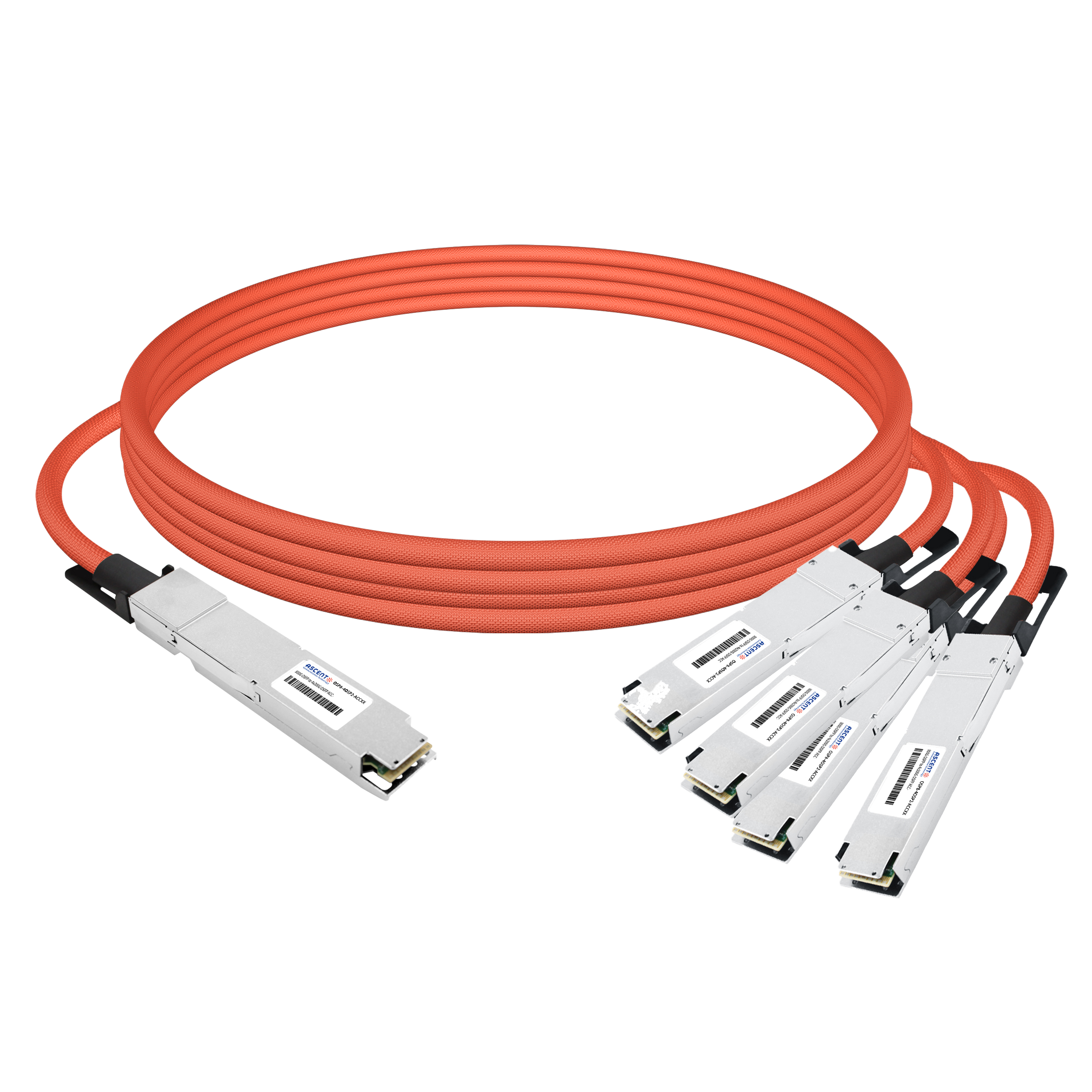
800G OSFP to 4x200G Breakout ACC
800G 4x200G OSFP Breakout Active Copper Cable
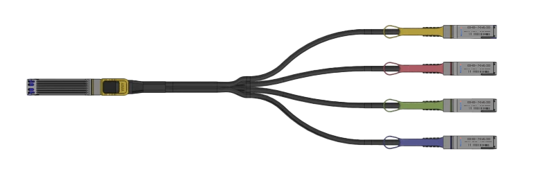
800G OSFP 4xQSFP112 DAC Cable
800G OSFP to 4xQSFP112 Cable Assembly
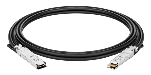
400G OSFP to 400G QSFP-DD DAC
400G OSFP to 400G QSFP-DD Passive DAC Twinax Cable

400G OSFP to 4x100G QSFP56 DAC
400G OSFP to 4x100G QSFP56 Passive DAC Breakout Cable
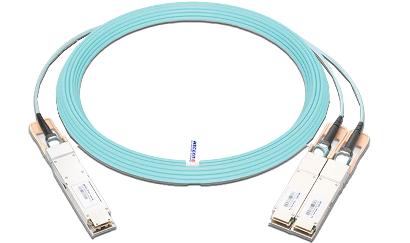
400G OSFP to 2x200G QSFP56 AOC Breakout Cable
400G OSFP to 2x200G QSFP56 AOC Breakout Cable
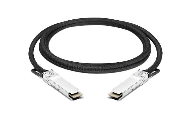
400G QSFP Q112 AEC Cable
400G QSFP-DD to QSFP-DD Active Electrical Cable

400G QSFP DD DAC Cable
400G QSFP-DD Passive Direct Attach Copper Cable

400G QSFP DD to 4X100G QSFP56 AOC
400G QSFP-DD to 4x100G QSFP56 Active Optical Cable

400G QSFP DD to 4X100G QSFP28 AOC
400G QSFP-DD to 4x100G QSFP28 Active Optical Cable

400G QSFP DD AOC Cable
400G QSFP-DD Active Optical Cable
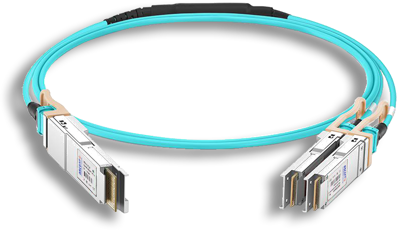
400G QSFP DD AOC Breakout Cable
400G QSFP-DD to 2x 200G QSFP56 Active Optical Breakout Cable

200G QSFP56 InfiniBand HDR AOC
200G QSFP56 to QSFP56 Active Optical Cable

200G QSFP56 PSM4 DAC
200G QSFP56 PSM4 Direct Attach Passive Copper Cables
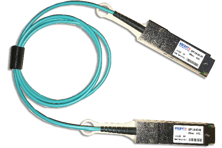
QSFP28 100G AOC Cable
100 Gb/s QSFP28 Active Optical Cable
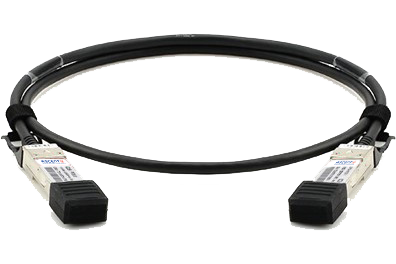
QSFP28 100G DAC Cable
100G QSFP28 Passive DAC Twinax Cable
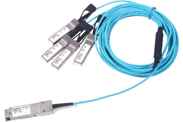
QSFP AQ AOC 4G 10
40G QSFP+ to 4x10G SFP+ Transceiver

QSFP+ 40G DAC Cable
40G QSFP+ to QSFP+ Passive Copper Cable (PCC)
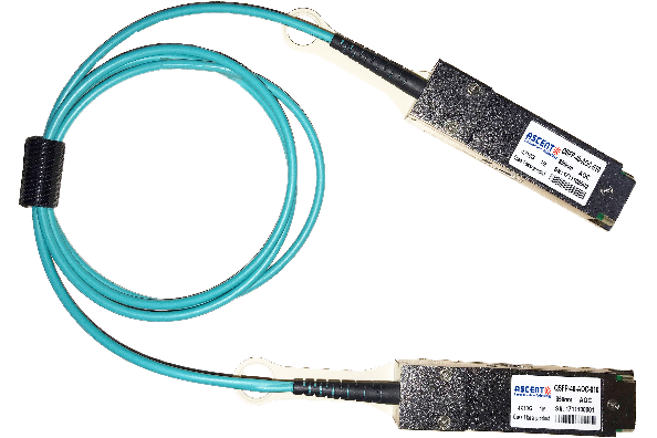
QSFP+ 40G AOC Cable
40G QSFP+ Active Optical Cable
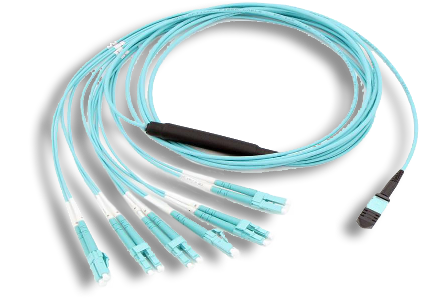
MTP/MPO Harness Assemblies
12/24 MTP/MPO LC Harness Cable Assembly
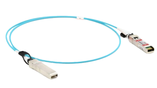
25G SFP28 AOC Cable
25 Gb/s SFP28 Active Optical Cable DDM
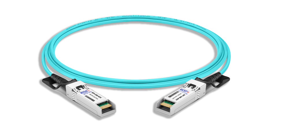
SFPP AT AOC Cable
10G SFP+ Active Optical Cable
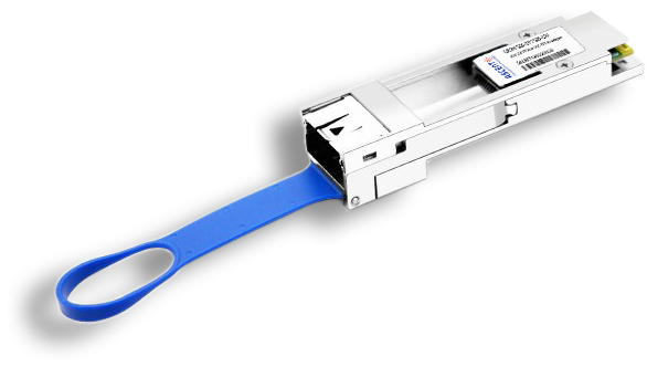
100G to 25G Adapter
100G QSFP28 to 25G SFP28 Adapter
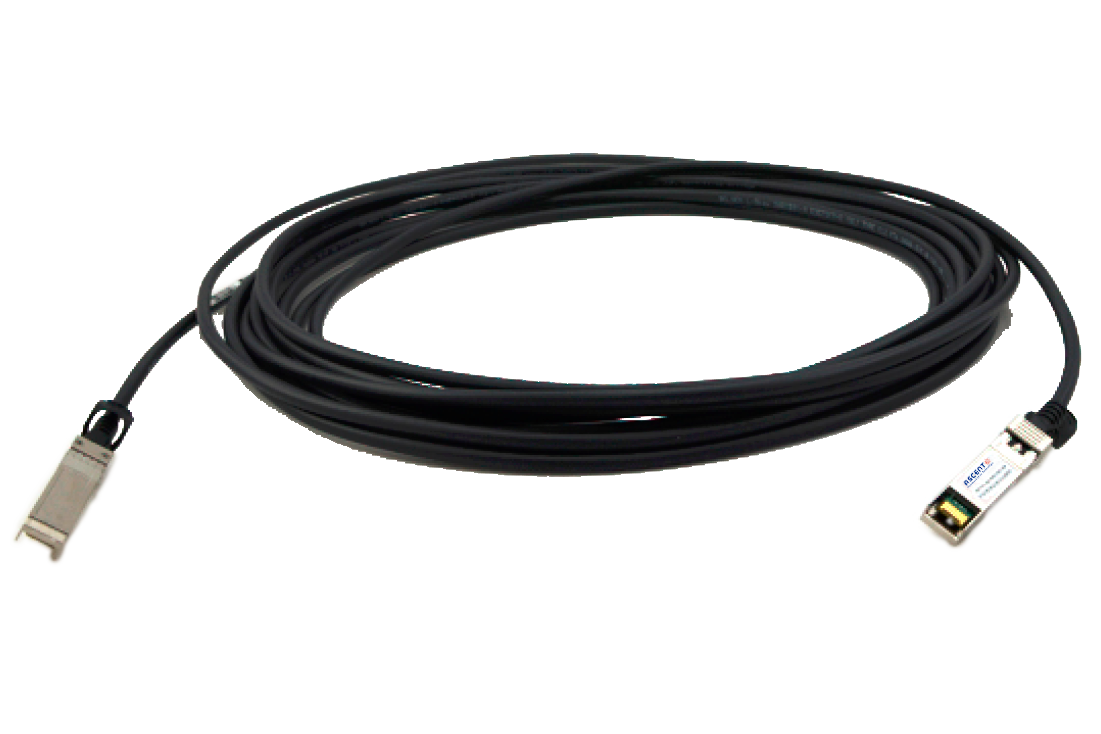
10G SFP+ Passive Copper Twinax Cable
SFPP-AT-DAC-2M 10G SFP+ Passive Direct Attach Copper Twinax Cable (PCC)
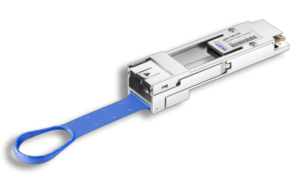
QSFP CVR 10G
QSFP to SFP/SFP+ Adapter Module
White Paper
Press Releases
Briefings 1
Briefings 2
Videos, etc.
QRG
Manual1
Manual2
Get in touch with our experts
Feedback