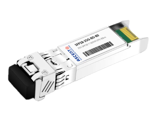
The SFP28 25Gb/s BIDI transceiver is a high-performance, long-reach optical module designed for up to 80 km transmission over single-mode fiber (SMF). Supporting data rates up to 25.78125 Gb/s, the module is compliant with IEEE 802.3cc, SFF-8472, and SFF-8419 standards, making it suitable for high-speed applications such as 25G Ethernet and CPRI links. Its compact SFP28 form factor with a single LC interface enables efficient bidirectional transmission over a single fiber. The transceiver utilizes a high-performance EML transmitter combined with an integrated SOA and PIN/TIA receiver, ensuring excellent optical performance and extended transmission reach. Operating at nominal wavelengths of approximately 1295 nm or 1309 nm, the module supports stable long-distance communication with high sensitivity and low noise characteristics. The electrical interface is compliant with SFI specifications, with AC-coupled high-speed differential signaling for reliable signal integrity. Designed for efficiency and reliability, the module offers low power consumption and supports both commercial and industrial operating environments. It also provides digital diagnostic monitoring (DDM) via a standard I²C interface, enabling real-time monitoring of key parameters such as temperature, voltage, and optical power. With its robust design and long-reach capability, the SFP28 25G BIDI transceiver is ideal for carrier-grade networks, long-distance data links, and next-generation access infrastructure.
· Support data rate up to 25.78125Gb/s
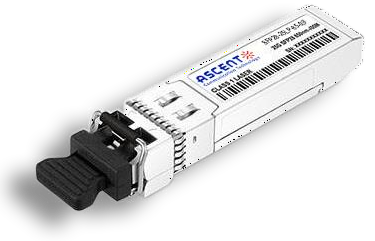
· Hot-Pluggable SFP Footprint and Single LC Connector
· Up to 80km reach for G.652 SMF
· EML TX and Integrated SOA & PIN TIA RX
· Temperature Range:
Commercial: 0°C ~ 70°C
Industrial: -40°C ~ 85°C
· Power consumption
Commercial: 2.2W
Industrial: 2.8W
· RoHS 6 compliance
· Compliant to IEEE 802.3cc, SFF-8472 and SFF-8419
· Complies with EU Directive 2015/863/EU
Parameter | Symbol | Min. | Typ. | Max. | Unit | Notes |
Storage Temperature | Tstg | -40 | +85 | °C | ||
Operating Case Temperature | TO | 0 | 70 | °C | Commercial | |
TO | -40 | 85 | °C | Industrial | ||
Storage Relative Humidity | RHS | 5 | 95 | % | ||
Operating Relative Humidity | RHO | 5 | 85 | % | ||
DC Supply Voltage | VCC | 0 | 3.6 | V |
Recommended Operating Conditions
Parameter | Symbol | Min. | Typ. | Max. | Unit | Notes |
Operating Case Temperature | Top | 0 | - | 70 | °C | Commercial |
-40 | 85 | Industrial | ||||
Power Supply Voltage | VCC | 3.13 | 3.3 | 3.47 | V | |
Transmission Distance | TD | - | - | 80 | km | Over SMF |
Electrical Characteristics
High-Speed Signal: Compliant to CEI-25G-VSR
Low-Speed Signal: Compliant to SFF-8431
Parameter | Symbol | Min. | Typ. | Max. | Unit | Notes | |
Supply Voltage | VCC | 3.135 | 3.465 | V | |||
Supply Current | ICC | 660 | mA | Commercial | |||
850 | Industrial | ||||||
Power Consumption | P | 2.2 | W | Commercial | |||
2.8 | Industrial | ||||||
Transmitter (Module Input) | |||||||
Differential Input Resistance | R_Rdin | 90 | 100 | 110 | W | ||
Input Differential Voltage | R_Vdiff | - | - | 900 | mVpp | ||
Tx_Disable | Normal Operation | VIL | -0.3 | - | 0.8 | V | |
Laser Disable | VIH | 2.0 | - | VCC+0.3 | V | ||
Receiver (Module Output) | |||||||
Differential Resistance | T_Rd | 90 | 100 | 110 | Ohm | ||
Output Differential Voltage | T_Vdiff | - | - | 900 | mVpp | ||
Differential Termination Resistance Mismatch | T_Rdm | - | - | 10 | % | ||
Rx los | Normal Operation | VOL | -0.3 | - | 0.4 | V | |
Loss Signal | VOH | 2 | VCCHOST | V | |||
Parameter | Symbol | Min. | Typ. | Max. | Unit | Notes | |
Transmitter | |||||||
Average Output Power | POUT | 2 | 7 | dBm | 1 | ||
Average Output Power(Laser Off) | POFF | -30 | dBm | ||||
Wavelength | λ | 1294.53 | 1295.56 | 1296.59 | nm | ||
1308.09 | 1309.14 | 1310.19 | |||||
Spectrum Bandwidth @ -20dB | Δλ | 1 | nm | ||||
Side mode suppression ratio(SMSR) | SMSR | 30 | dB | ||||
Extinction ratio | ER | 8 | dB | ||||
RIN20OMA | RIN | -128 | dB/Hz | ||||
Transmitter and dispersion penalty (TDP) | 2.7 | dB | |||||
Receiver | |||||||
Wavelength | λ | 1308.09 | 1309.14 | 1310.19 | nm | ||
1294.53 | 1295.56 | 1296.59 | |||||
Received Sensitivity | PIN | -27 | dBm | 1 | |||
Optical Power Overload | PIN(SAT) | -4 | dBm | ||||
Damage threshold | 3 | dBm | 2 | ||||
Rx_LOS of Signal Assert | PA | -40 | dBm | ||||
Rx_LOS of Signal De-assert | PD | -28 | dBm | ||||
Rx_LOS of Signal Hysteresis | PHy | 0.5 | 5 | dB | |||
Optical Return Loss Tolerance | ORLT | 20 | dB | ||||
1. Test pattern: PRBS31. BER<5x10⁻⁵.
2. The receiver shall be able to tolerate, without damage, continuous exposure to an optical input signal having this average power level. The receiver does not have to operate correctly at this input power.
Parameter | Symbol | Min. | Typ. | Max. | Unit | Notes |
TX_Disable Assert Time | t_off | 100 | us | |||
TX_Disable Negate Time | t_on | 2 | ms | |||
Time to Initialize Include Reset of TX_FAULT | t_int | 300 | ms | |||
TX_FAULT from Fault to Assertion | t_fault | 100 | us | |||
TX_Disable Time to Start Reset | t_reset | 10 | us | |||
Receiver Loss of Signal Assert Time | TA,RX_LOS | 100 | us | |||
Receiver Loss of Signal Deassert Time | Td,RX_LOS | 100 | us | |||
Rate-Select Chage Time | t_ratesel | 10 | us |


64G SFP56 850nm 100m
40/100G SFP28 SWDM4 100m

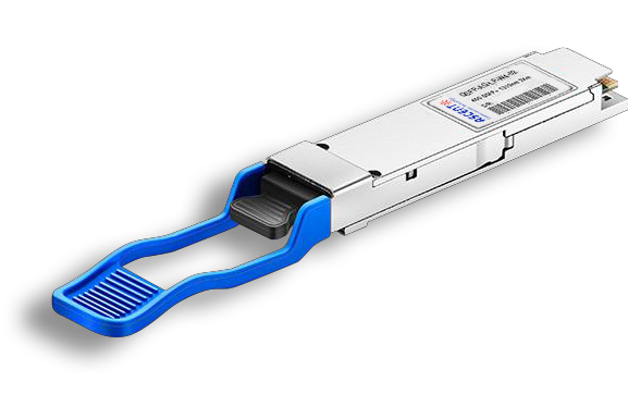
40G QSFP+ ER4 Industrial 40 km

40G QSFP+ ER4 40 km

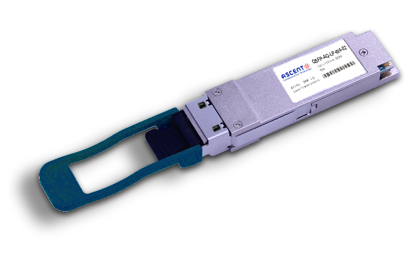
40G QSFP+ LR4 Industrial 10 km

40G QSFP+ LR4 10 km

40G QSFP+ PSM4 2 km
40G QSFP+ PLR4 1310 nm 10 km
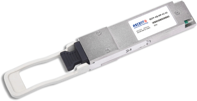
40G QSFP+ CSR4 300m
40GBASE-UNIV QSFP+ MMF and SMF
40G QSFP+ CWDM 2 km
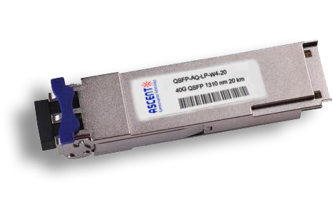
40G QSFP CWDM 20 km
40G QSFP+ SR4 300 m

40G QSFP+ BIDI 150m
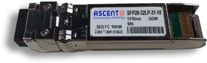
32G SFP28 1310 nm 10 km

32G SFP28 SR 850 nm 100 m
.png)
25G SFP28 CWDM 10 km(E)
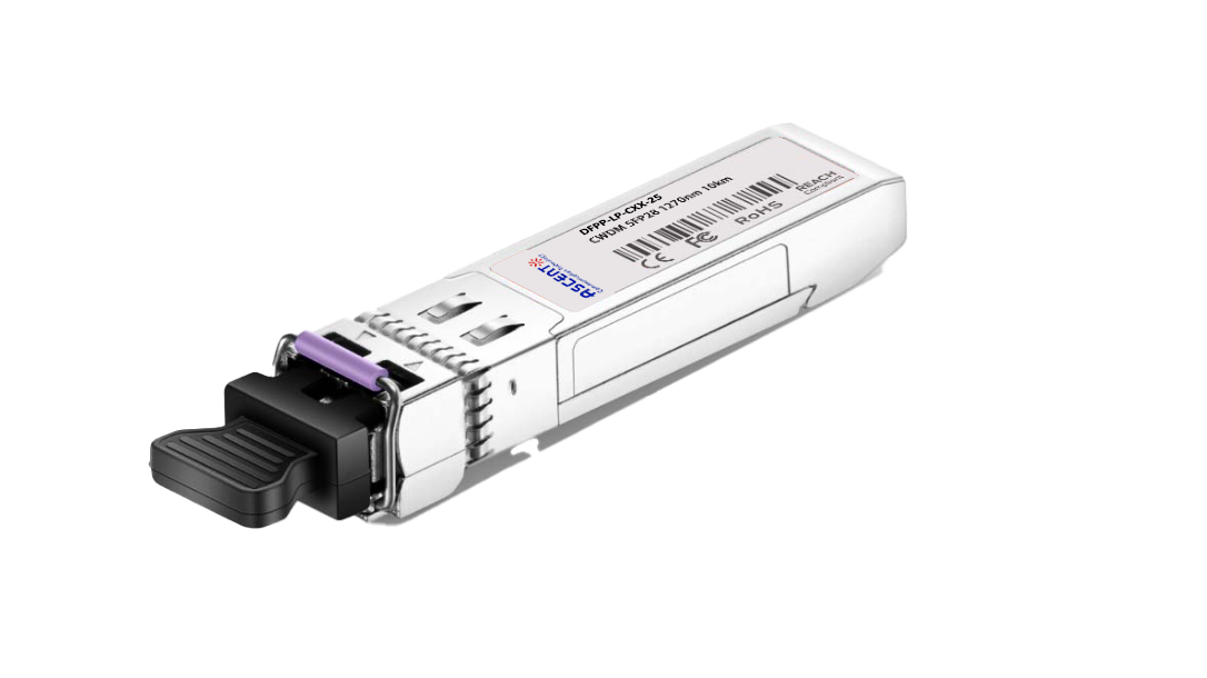
25G SFP28 CWDM 10 km(D)

25G SFP28 ZR 1310nm 80km
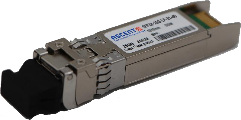
25G SFP28 1310 nm 40km
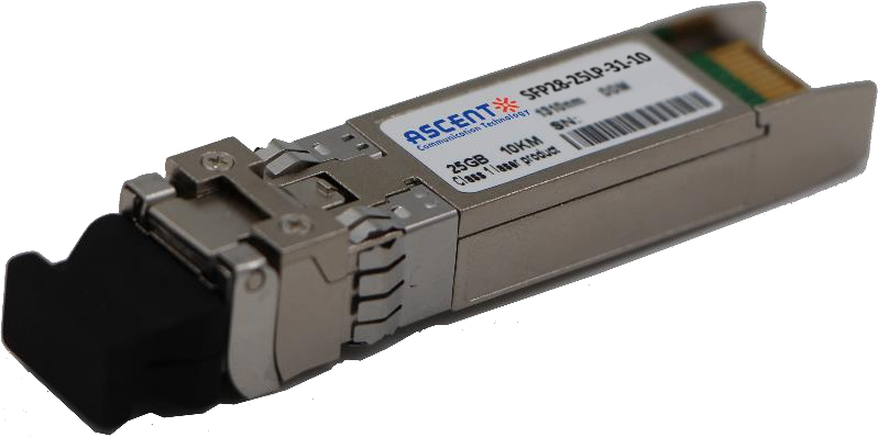
25G SFP28 1310 nm 10 km
25G SFP28 850 nm 300m

10/25G SFP28 1310nm 40km

10/25G SFP28 1310nm 10km

10/25G SFP28 850 nm 300m

10/25G SFP28 850 nm 100m