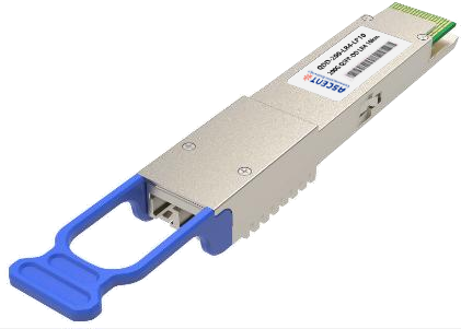
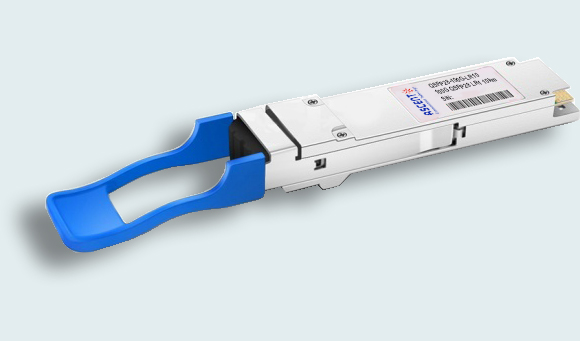
Ascent’s QSFP28 100G DR Single Lambda Ethernet module is a transceiver module designed for 500m optical communication applications, and it is compliant with IEEE 802.3cu 100GBASE-DR standard. QS28-100G-DR1-05 can be used in Data Centers, High- speed interconnects within and between switches, routers and transport equipment, Server-Server Clusters, Super-computing interconnections and other network applications. This module incorporates one channel optical signal, on 1310nm center wavelength. The transmitter path incorporates an EML Driver integrated in the DSP and a cooled EML together. On the receiver path, the input optical signal is coupled to a Pin photodiode detector. can convert 4-channel 25.78125Gbit/s electrical data to 1-channel 106.25Gbit/s optical signals. It has been designed to meet the harshest external operating conditions including temperature, humidity and EMI interference. The module offers very high functionality and feature integration, accessible via a two-wire serial interface.
· IEEE 100GBASE-DR compliant
· 100GE Single Protocol (103.125 Gb/s)
· CAUI-4 compliant - 4x 25.78125 Gb/s
· 100GAUI-4 compliant – 4x 26.5625 Gb/s
· RS-FEC(544,514) FEC coder/decoder function
· < 3.5 W MAX
· 0 to 70°C
· Single cooled 100Gb/s 1310nm EML
· Single PIN PD + low-power TIA
· SFF-8636 management interface
Absolute Maximum Ratings
Parameter | Symbol | Min. | Typ. | Max. | Unit | Note |
Supply Voltage | VCC | 0 | - | +3.6 | V | 3.3 |
Storage Temperature | -40 | - | +85 | °C | ||
Optical Receiver Input | - | +5.0 | dBm | Average |
Operating Environment
Parameter | Symbol | Min. | Typ. | Max. | Unit | Note |
Supply Voltage | Vcc | 3.135 | 3.3 | 3.465 | V | |
Supply Voltage Noise Tolerance | PSNR | - | - | 66 | mV | 10 Hz –10 MHz |
Power Consumption | - | - | 3.5 | W | Target | |
Supply Current | -- | - | 1010.1 | mA | Steady state | |
Case Temperature | TC | 0 | 25 | 70 | °C |
Optical Characteristics
Parameter | Value | Unit | Note |
Transmitter | |||
PAM4 Signaling Rate (Range) | 53.125 ± 100 ppm | GBd | |
Lane Wavelengths (Range) | 1304.5- 1317.5 | nm | |
Side-Mode Suppression Ratio (SMSR), (Min) | 30 | dB | |
Average Launch Power (Max) | 4 | dBm | |
Average Launch Power (Min) | -2.9 | dBm | 1 |
Outer Optical Modulation Amplitude (OMAouter) (Max) | 4.2 | dBm | |
Outer Optical Modulation Amplitude (OMAouter) (Min) | -0.8 | dBm | 2 |
Launch Power in OMAouter Minus TDECQ (min) ER≥5dB2 | -2.2 | dBm | |
Launch Power in OMAouter Minus TDECQ (min) ER<5dB2 | -1.9 | dBm | |
Transmitter and Dispersion Penalty Eye Closure for PAM4 (TDECQ), (Max) | 3.4 | dB | |
TDECQ – 10*Log10(Ceq) (Max) | 3.4 | dB | 4 |
Average Launch Power of OFF Transmitter (Max) | -15 | dBm | |
Extinction Ratio (Min) | 3.5 | dB | |
Optical Return Loss Tolerance (Max) | 15.5 | dB | |
Transmitter Reflectance (Max) | -26 | dB | 3 |
Transmitter Transition Time (Max) | 17 | ps | |
RIN15.5 OMA (Max) | -136 | dB/Hz | |
Receiver | |||
PAM4 Signaling Rate (Range) | 53.125 ± 100 ppm | GBd | |
Lane Wavelengths (Range) | 1304.5 to 1317.5 | Nm | |
Damage Threshold (Min) | 5 | dBm | 5 |
Average Receive Power (Max) | 4 | dBm | |
Average Receive Power (Min) | -5.9 | dBm | 6 |
Receive Power (OMAouter) (Max) | 4.2 | dBm | |
Receiver Reflectance (Max) | -26 | dB | |
Receiver Sensitivity (OMAouter) (Max) | −3.9, ????????????????−5. | dBm | 7 |
Stressed Receiver Sensitivity (OMAouter) (Max) | -1.9 | 8 | |
Conditions of Stressed Receiver Sensitivity Test | 9 | ||
Stressed Eye Closure for PAM4 (SECQ) | 3.4 | dB | |
SECQ – 10*Log10(Ceq) (Max) | 3.4 | dB | 10 |
Notes:
1. Average launch power, each lane (min) is informative and not the principal indicator of signal strength. A transmitter with launch power below this value cannot be compliant; however, a value above this does not
ensure compliance.
2. Even if the TDECQ < 1.4 dB for an extinction ratio of ≥ 5 dB or TDECQ < 1.1dB for an extinction ratio of < 5 dB, the OMAouter (min) must exceed this value.
3. Transmitter reflectance is defined looking into the transmitter.
4. Ceq is a coefficient defined in IEEE Std 802.3-2018 clause 121.8.5.3 which accounts for reference equalizer noise enhancement.
5. The receiver shall be able to tolerate, without damage, continuous exposure to an optical signal having this average power level.
6. Average receive power, each lane (min) is informative and not the principal indicator of signal strength. A received power below this value cannot be compliant; however, a value above this does not ensure compliance.
7. Receiver sensitivity (OMAouter), (max) is informative and is defined for a transmitter with a value of SECQ up to 3.4 dB.
8. Measured with conformance test signal at TP3 (see IEEE Std 802.3cd clause 140.7.10) for the BER specified in IEEE Std 802.3cd clause 140.1.1.
9. These test conditions are for measuring stressed receiver sensitivity. They are not characteristics of the receiver.
10. Ceq is a coefficient defined in IEEE Std 802.3-2018 clause 121.8.5.3 which accounts for reference equalizer noise enhancement.
Parameter | Symbol | Min. | Typ. | Max. | Unit | Note |
Receiver Loss of Signal Indicator Assert Level | RX_LOS | -30 | - | -7.5 | dBm | Average power |
Receiver Loss of Signal Indicator De-assert Level | RX_LOS | - | - | -7 | dBm | Average power |
Parameter | Min. | Typ. | Max. | Unit | Note |
Transmitter (each lane) | |||||
Differential Pk-Pk Input Voltage Tolerance (Min) | 900 | - | - | mV | at TP1a |
Differential Termination Mismatch | - | - | 10 | % | at TP1 |
Single-Ended Input Voltage Tolerance Range | -0.4 to 3.3 | - | - | V | at TP1a |
DC Common Mode Voltage | -350 | - | 2850 | mV | at TP1 |
Receiver (Each Lane, at TP4) | |||||
AC Common-Mode Output Voltage (RMS) | - | - | 17.5 | mV | |
Differential Output Voltage | - | - | 900 | mV | |
Eye Width | 0.57 | - | - | UI | |
Eye Height, Differential | 228 | - | - | mV | |
Vertical Eye Closure | - | - | 5.5 | dB | |
Differential Termination Mismatch | - | - | 10 | % | |
Transition Time (20% to 80%) | 12 | - | - | ps | |
DC Common Mode Voltage | -350 | - | 2850 | mV |
Notes: Electrical Rx output is squelched for loss of optical input signal.


200G QSFP DD LR4 10km
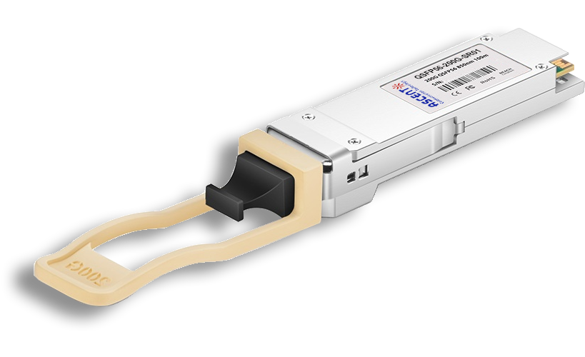
200G QSFP56 SR4 850 nm 100 m

100G QSFP28 LX4 2km

100G QSFP28OA LR4 10km

100G QSFP28 ZR4 1310 nm 80 km

100G QSFP28 ER4L 1310 nm 40 km
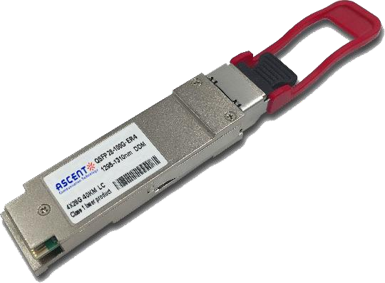
100G QSFP28 ER4 1310 nm 40 km
100G QSFP28 LR4 1310 nm 10 km
100G QSFP28 LR Single λ 10 km
100G QSFP28 CWDM4 1310 nm 2 km
100G QSFP28 PSM4 1310 nm 2 km
100G QSFP28 SR4 850 nm 100 m

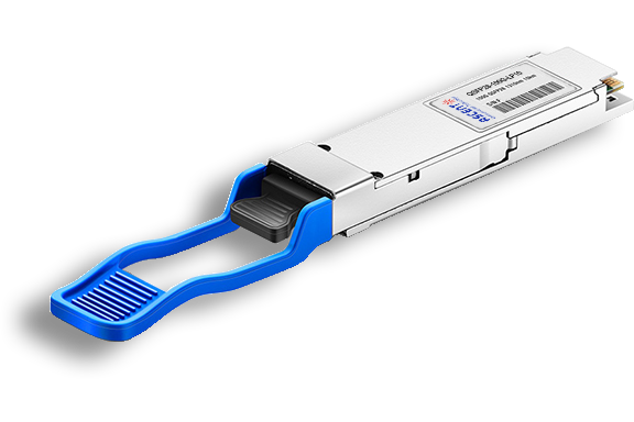
100G QSFP28 FR Single λ 1310 nm 2 km

100G QSFP28 SR01 BIDI MMF 850nm 100m

100G QSFP28 BIDI 80km

100G QSFP28 BIDI 40km

100G QSFP28 EZR4 100km

100G SFP56 ER1 30km

100G SFP56 LR1 10km
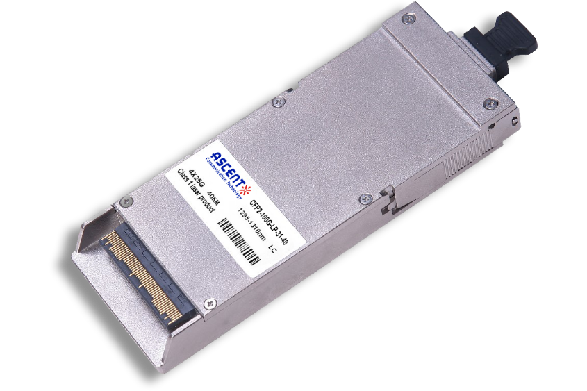
100G CFP2 ER4 40 km
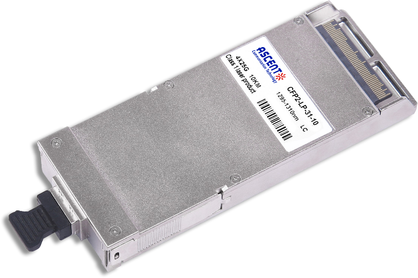
100G CFP2 LR4 10 km
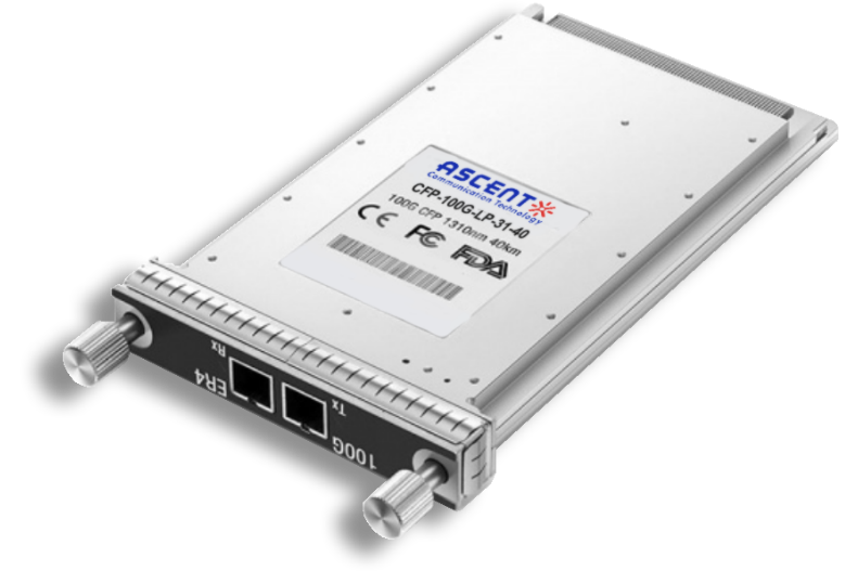
100G CFP ER4 40 km
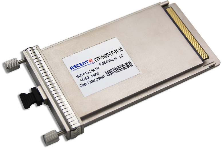
100G CFP LR4 10 km