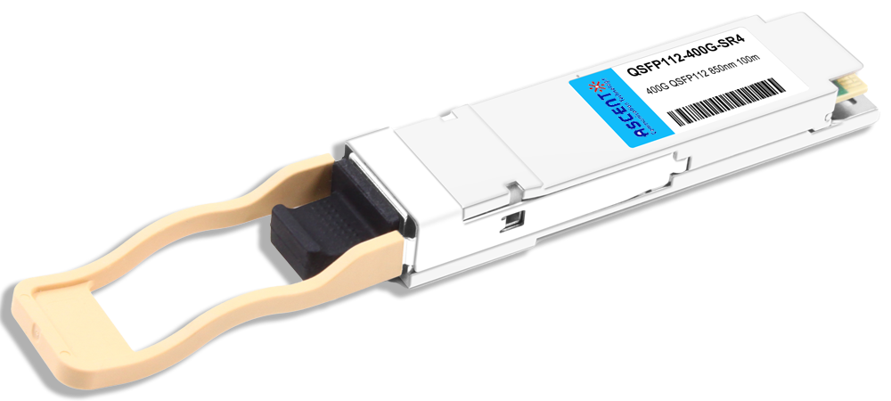
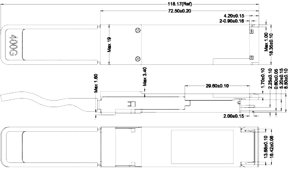
Ascent’s 400 Gbps QSFP112 SR4 transceiver is suitable for 400G ethernet and data center interconnect applications. It supports link lengths of up to 100m over MMF with MTP/MPO-12 connector. This transceiver is compliant with QSFP112 MSA, CMIS 4.0 Interface and 400GAUI-4 standards.
• 4x100G PAM4 retimed 400GAUI-4 electrical interface
• MPO-12 APC connector
• 4 channel VCSEL arrays and 4 channels PIN photo detector arrays
• Maximum link length of 60 m on OM3 or 100 m on OM4
• Hot-pluggable QSFP112 form factor
• Compliant with QSFP112_MSA_Specification_Rev2.1.1
• Compliant with CMIS 5.2
• Compliant with IEEE 802.3db
• Compliant with IEEE 802.3ck
• Less than 8W in temperature range of 0 to 70°C
Parameter | Symbol | Min. | Max. | Unit |
Storage Temperature | Ts | ‑40 | 85 | °C |
Case Operating Temperature | Top | 0 | 70 | °C |
Relative Humidity (non‑condensation) | RH | 15 | 85 | % |
Supply Voltage | Vcc | ‑0.5 | 3.6 | V |
Receiver Damage Threshold, per Lane | PRdmg | 5 | dBm |
Operating Environments
Parameter | Symbol | Min. | Max. | Unit |
Operating Case Temperature | Top | 0 | 70 | °C |
Relative Humidity(non‑condensing) | RH | 15 | 85 | % |
Power Supply Voltage | Vcc | 3.135 | 3.465 | V |
Total Power Consumption1 | Pc | ‑ | 8 | W |
Supply Current per end | 2.55 | A | ||
Bit Rate | BR | 425 | Gbps | |
Fiber Length on OM3 MMF | 60 | m | ||
Fiber Length on OM4 MMF | 100 | m | ||
I2C Clock Frequency | 0 | 400 | kHz |
Note:
Under condition of 3.465V operating supply voltage, and 70°C case temperature.
Optical Transmitter
Parameter | Symbol | Min. | Typ. | Max. | Unit | |
Data Rate per Lane | DR | 53.125 | GBd | |||
Modulation Format | PAM4 | |||||
Center Wavelength1 | y | 840 | 860 | 868 | nm | |
RMS Spectral Width | σ | 0.6 | nm | |||
Average Launch Power, each Lane | Pavg | ‑4.6 | 4 | dBm | ||
Optical Power OMA, each Lane, Max. | POMA | 3.5 | dBm | |||
OMAouter, each Lane, Min. | max (TECQ, TDECQ) <1.8 dB | max [‑2.6, max(TECQ, TECQ) – 4.4] |
dBm | |||
1.8 < max (TECQ, TDECQ) < 4.4 dB | ||||||
Transmitter and Dispersion Eye Closure (TDECQ), each Lane | TDECQ | 4.4 | dB | |||
Transmitter Eye Closure for PAM4 (TECQ), each Lane | TECQ | 4.4 | dB | |||
Extinction Ratio | ER | 2.5 | dB | |||
Transmitter Power Excursion, each Lane | 2.3 | dBm | ||||
Optical Return Loss Tolerance | ORLT | 14 | dB | |||
Optical Power for TX DISABLE | ‑30 | dBm | ||||
Encircled fluxb2 | ≥86% at 19 µm ≤30% at 4.5 µm | |||||
Notes:
1. Defined according to the performance of the laser used.
2. Measured into type A1a.2 or type A1a.3, or A1a.4, 50 um fiber, in accordance with IEC 61280‑1‑
Optical Receiver
Parameter | Symbol | Min. | Typ. | Max. | Unit | Note | |
Data Rate per Lane | BR | 53.125 | GBd | ||||
Modulation Format | PAM4 | ||||||
Center Wavelength | y | 842 | 850 | 948 | nm | ||
Damage Threshold | 5 | dBm | |||||
Average Receive Power, each Lane | –6.4 | 4 | dBm | ||||
Receive Power, each Lane (OMAouter) | 3.5 | dBm | |||||
Receiver Reflectance | Rr | – 15 | dB | ||||
Receiver Sensitivity, each Lane | RS = max (‑4.6, TECQ – 6.4) | dBm | 1 | ||||
Stressed Receiver Sensitivity, each Lane | –2.0 | dBm | |||||
Rx LOS | Assert | ‑15 | dBm | ||||
De‑assert | ‑7.5 | dBm | |||||
Hysteresis | 0.5 | 5 | dB | ||||
Notes:
1. Receiver sensitivity is informative and is defined for a transmitter with a value of TECQ. Measured with conformance test signal at TP3 for BER = 2.4E‑4 Pre‑FEC.
Electrical Specification
Parameters | Min. | Typ. | Max. | Unit |
Pre FEC Bit Error Ratio | 2.4E‑4 | |||
Post FEC Bit Error Ratio | 1E‑12 | |||
Transmitter (each Lane) | ||||
Differential pk‑pk Input Voltage Tolerance | 750 | mV | ||
Differential Termination Mismatch | 10 | % | ||
Eye Height | 10 | mV | ||
Common‑Mode to Differential‑Mode Return Loss | IEEE802.3ck Equation (120G– 1) | dB | ||
Vertical Eye Closure | 12 | dB | ||
Effective Return Loss | 7.3 | dB | ||
Transition Time | 10 | ps | ||
Receiver (each Lane) | ||||
Differential data output swing | 300 | 900 | mVpp | |
Differential Termination Mismatch | 10 | % | ||
Eye Height | 15 | mV | ||
Vertical Eye Closure | 12 | dB | ||
Common‑Mode to Differential‑Mode Return Loss | IEEE802.3ck Equation (120G– 1) | |||
Effective Return Loss | 8.5 | dB | ||
Transition Time | 8.5 | ps | ||
800G OSFP DAC Cable
800G OSFP ACC Cable

800G OSFP DR8 1310 nm 500 m

800G OSFP SR8 850 nm 100 m
400G QSFP56-DD 10km

400G QSFP-DD ZR+
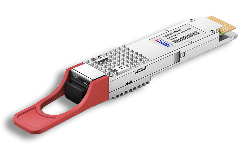
400G QSFP-DD ER8 40 km
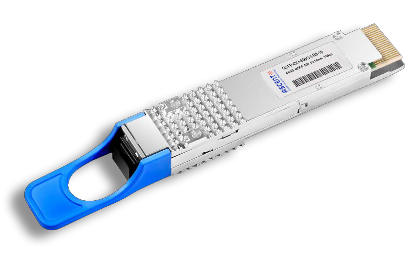
400G QSFP-DD LR8 1310 nm 10 km

400G QSFP-DD LR4 CWDM 10 km
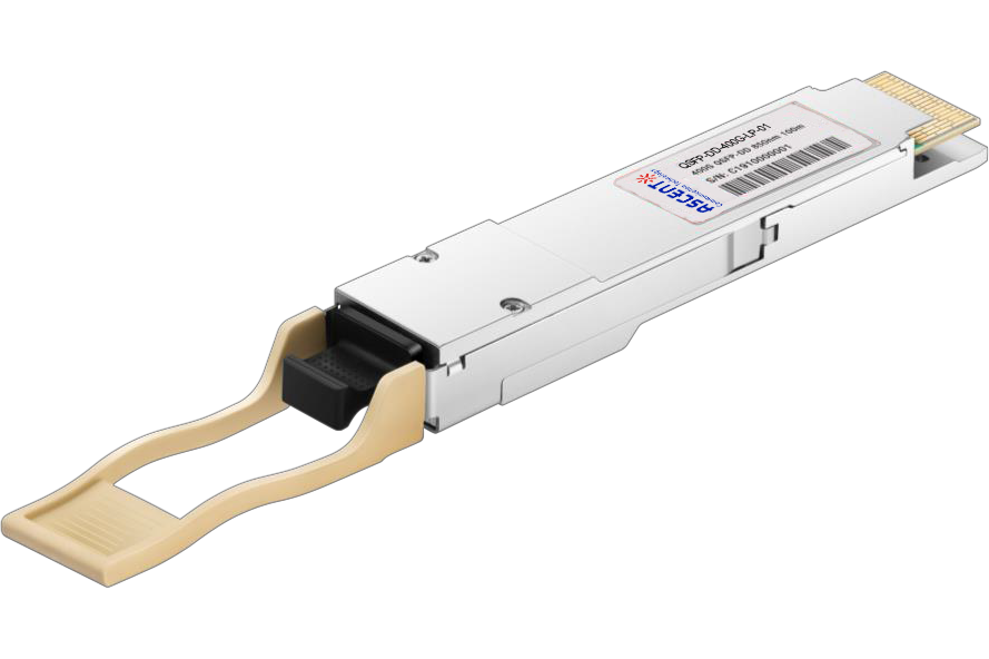
400G QSFP-DD SR8 850 nm 100 m
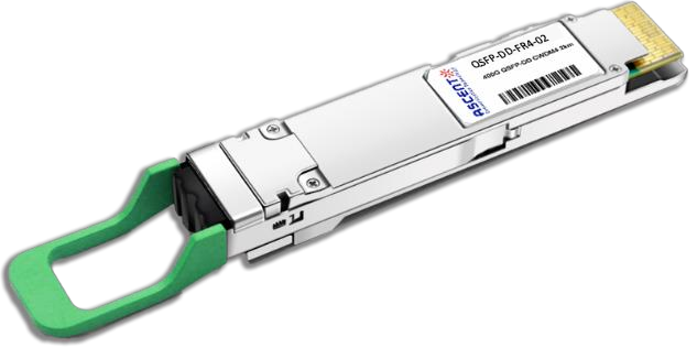
400G QSFP-DD FR4 2km

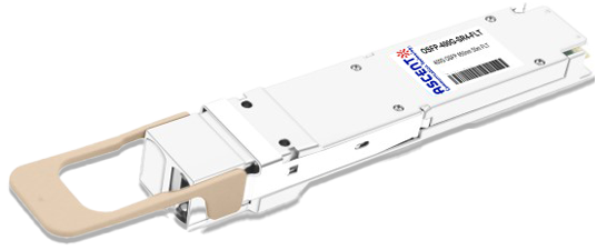
400G QSFP-DD DR4 500m

400G QSFP-DD DCO ZR

4X100G QSFP-DD LR4 10km
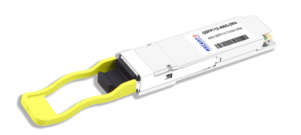
400G QSFP112 DR4 1310 nm 500 m
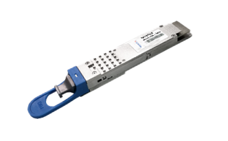
400G OSFP SR4 FLT 50m Transceiver
400G OSFP SR8 100m Transceiver