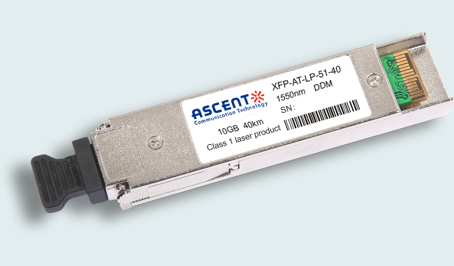
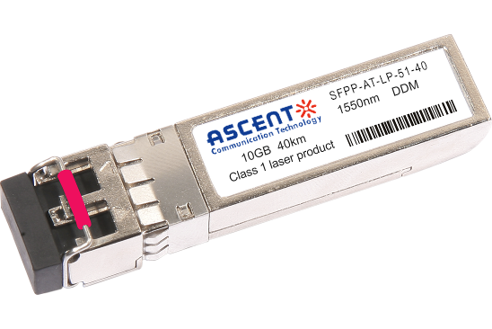
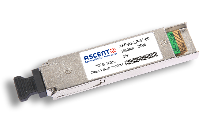
ASCENT’s XFP-AT-LP-51-40 Small Form Factor 10G (XFP) transceivers are designed for use in 10-Gigabit Ethernet links up to 40km over single mode fiber. It is widely used in applications such as Internet Service Provider (ISP) Fiber To The Home aggregation and backbone, Various Data Communication 10G Ethernet & SONET OC-192 IR-2/SONET OC-192 IR3/SDHSTM S-64.2b/SDH STM S-64.3b Links, Data Center networking for Ethernet and Fiber Channel SAN Networking and other optical links. The module consists of 1550 EML Laser, InGaAs PIN and Preamplifier in a high-integrated optical subassembly.It is compliant with the current XFP MultiSourceAgreement (MSA) Specification. They comply with 10-Gigabit Ethernet 10GBASE-ER/EW per IEEE 802.3ae and 10G Fiber Channel 40KM. Digital diagnostics functions are available via a 2-wire serial interface, as specified in the XFP MSA. It also defines a sophisticated system of alarm and warning flags, which alerts end-users when particular operating parameters are outside of a factory set normal range. The transceivers are RoHS compliant and lead free per Directive 2002/95/EC3.
• Hot-pluggable XFP footprint
• Supports 9.95 Gb/s to 11. 3Gb/s bit rates
• Supports Lineside and XFI loopback
• RoHS-6 Compliant (lead-free)
• Power dissipation<2.5 W
• 3.3 V & 1.8 V power supply
• Max. link length of 40 km
• Cooled 1550 nm EML and APD receiver
• Full duplex LC connector
• No reference clock required
• Built-in digital diagnostic functions
• Standard bail release mechanism
• Case operating temperature range: Commercial: 0°C to +70°C, Industrial: -40°C to +85°
Absolute Maximum Ratings
Parameter | Symbol | Min. | Typ. | Max. | Unit | Note |
Maximum Supply Voltage 2 | Vcc2 | ‑0.3 | 3.6 | V | ||
Maximum Supply Voltage 3 | Vcc3 | ‑0.3 | 2.0 | V | ||
Storage Temperature | TS | ‑40 | 85 | °C | ||
Case Operating Temperature | Tcase | 0 | 70 | °C | Commercial | |
‑40 | 85 | °C | Industrial | |||
Operating Relative Humidity | RHop | 5 | 95 | % |
Electrical Characteristics
Parameter | Symbol | Min. | Typ. | Max. | Unit | Note |
Supply Voltage – 1.8V supply | Vcc2 | 3.3 | 1.89 | V | ||
Supply Voltage – 3.3V supply | Vcc3 | 3.1 | 3.5 | V | ||
Supply Current – 1.8V supply | Icc2 | 180 | mA | |||
Supply Current – 3.3V supply | Icc3 | 640 | mA | |||
Module Total Power | P | 2.5 | W | 1 | ||
Transmitter | ||||||
Input Differential Impedance | Rin | 100 | Ω | 2 | ||
Differential Data Input Swing | Vin,pp | 120 | 820 | mV | ||
Transmit Disable Voltage | VD | 2.0 | Vcc | V | 3 | |
Transmit Enable Voltage | VEN | GND | GND+ 0.8 | V | ||
Transmit Disable Assert Time | 10 | µs | ||||
Receiver | ||||||
Differential Data Output Swing | Vout,pp | 340 | 850 | mV | 4 | |
LOS Fault | VLOS fault | Vcc ‑ 0.5 | VccHOST | V | 5 | |
LOS Normal | VLOS norm | GND | GND+0.5 | V | 5 | |
Notes:
1. Maximum total power value is specified across the full temperature and voltage range.
2. After internal AC coupling.
3. Or open circuit.
4. Into 100 Ω differential termination.
5. Loss Of Signal is an open collector to be pulled up with a 4.7 kΩ to 10 kΩ resistor to 3.15 V to 3.6V. Logic 0 indicates normal operation; logic 1 indicates no signal detected.
Optical Characteristics
Parameter | Symbol | Min | Typ | Max | Unit | Note |
Transmitter | ||||||
Output Optical Power | Pout | ‑1 | 4 | dBm | ||
Optical Wavelength | λ | 1530 | 1570 | nm | ||
Side mode Suppression Ratio | SMSR | 30 | dB | |||
Optical Extinction Ratio | ER | 8.2 | dB | |||
Avg. Launch Power of OFF Transmitter | POFF | ‑30 | dBm | |||
Eye Mask Margin | 30 | % | ||||
Receiver | ||||||
Receiver Sensitivity | RSEN | ‑16.5 | dBm | 1 | ||
Input Saturation Power (Overload) | Psat | +0.5 | dBm | |||
Wavelength Range | λC | 1270 | 1610 | nm | ||
Receiver Reflectance | Rrx | ‑27 | dB | |||
LOS De‑Assert | LOSD | ‑18 | dBm | |||
LOS Assert | LOSA | ‑32 | dBm | |||
LOS Hysteresis | 0.5 | dB | ||||
Notes:
1. Measured with BER < 10‑12 @ 10.3 Gbps, 231‑ 1 PRBS.
Regulatory Compliance
Feature | Reference | Performance |
Electrostatic Discharge (ESD) | IEC/EN 61000‑4‑2 | Compatible with standards |
Electromagnetic Interference (EMI) | FCC Part 15 Class B EN 55022 Class B (CISPR 22A) | Compatible with standards |
Laser Eye Safety | FDA 21CFR 1040.10, 1040.11 IEC/EN 60825‑1, 2 | Class 1 laser product |
Component Recognition | IEC/EN 60950, UL | Compatible with standards |
ROHS | 2002/95/EC | Compatible with standards |
EMC | EN61000‑3 | Compatible with standards |


10G SFP+ LR 1310 nm 40 km

10G SFP+ LR 1310 nm 20 km
10G SFP+ LR 1310 nm 10 km
10G SFP+ LRM 1310 nm 2 km
10G SFP+ ER 1550 nm 40 km
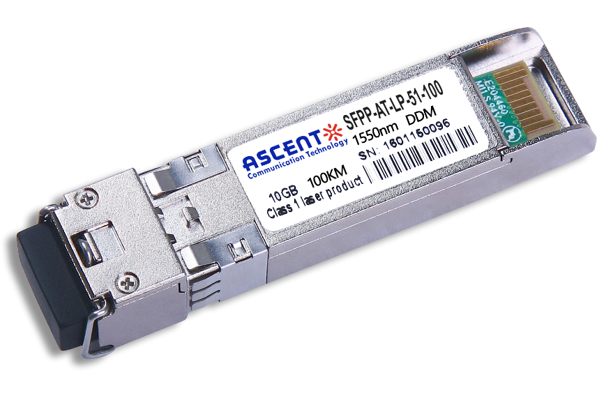
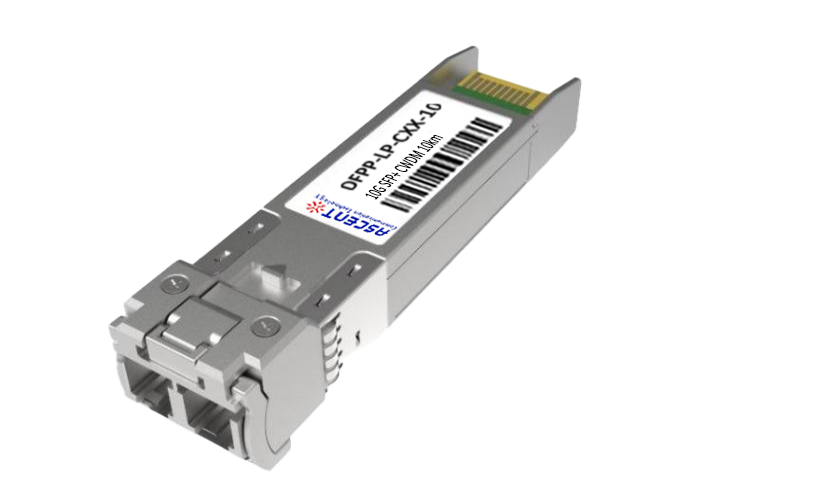
10G SFP+ CDR 1550 nm 100 km
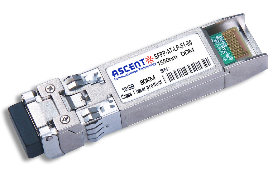
10G SFP+ ZR 1550 nm 80 km
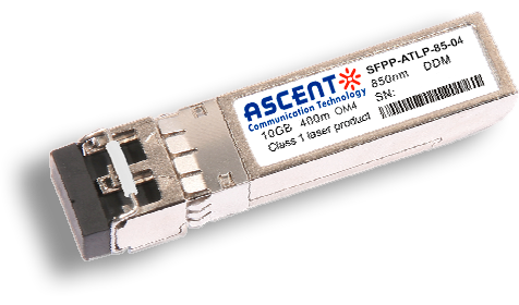
10G SFP+ 850 nm 400 m
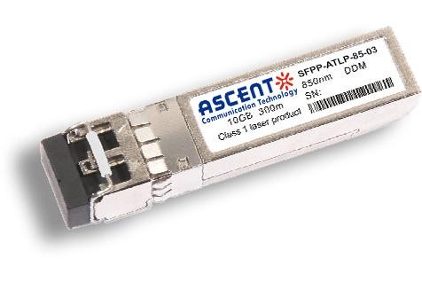
10G SFP+ 850 nm 300 m
10G SFP+ Tunable DWDM 80 km
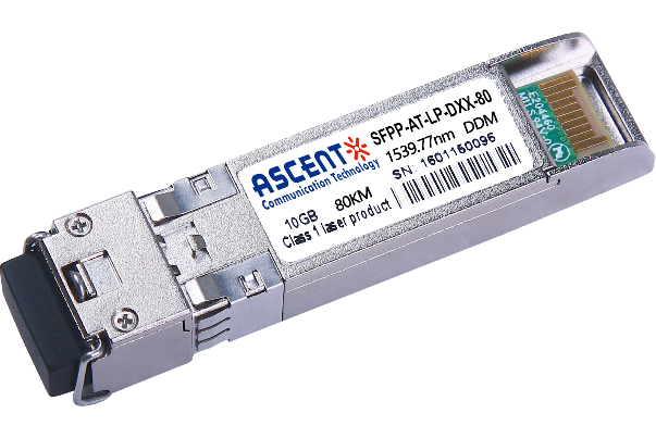
10G SFP+ DWDM 80 km
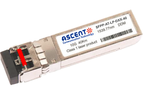
10G SFP+ DWDM 40 km

10G SFP+ CWDM 80 km
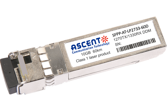
10G SFP+ CWDM 2733 60 km
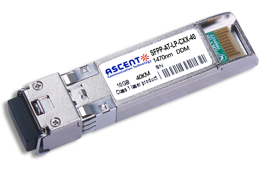
10G SFP+ CWDM 40 km
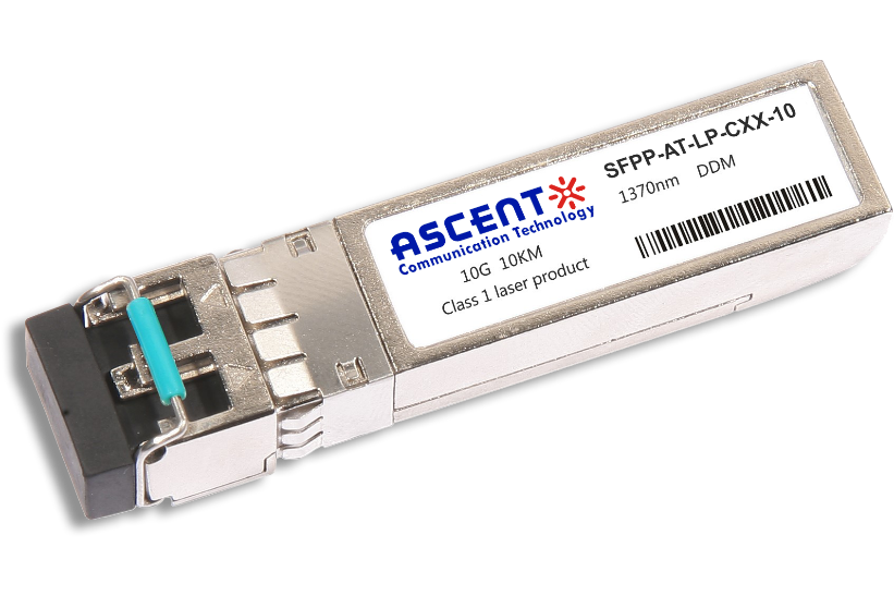
10G SFP+ CWDM 10 km
10G SFP+ Single mode CWDM 10 km
10G SFP+ CWDM 4955 80 km
10G SFP+ CWDM 2733 40 km
10G SFP+ CWDM 2733 10 km

10G XFP BIDI 80KM

10G XFP BIDI 40KM

10G XFP BIDI 20KM

10G XFP BIDI 10KM

10G XFP LR 1310 nm 20 km

10G XFP LR 1310 nm 10 km
10G XFP ZR 1550 nm 80 km
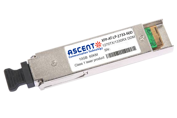
10G XFP CWDM 2633 60 km
10G SFP+ CWDM 1610 80 km
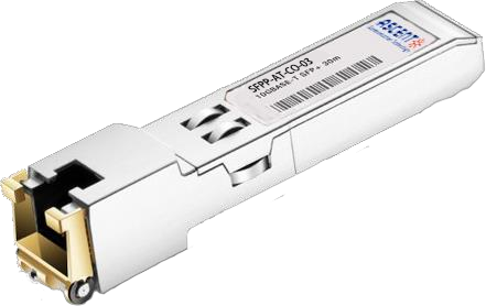
10G SFP+ Copper RJ45 30 m

10G X2 850nm 300m
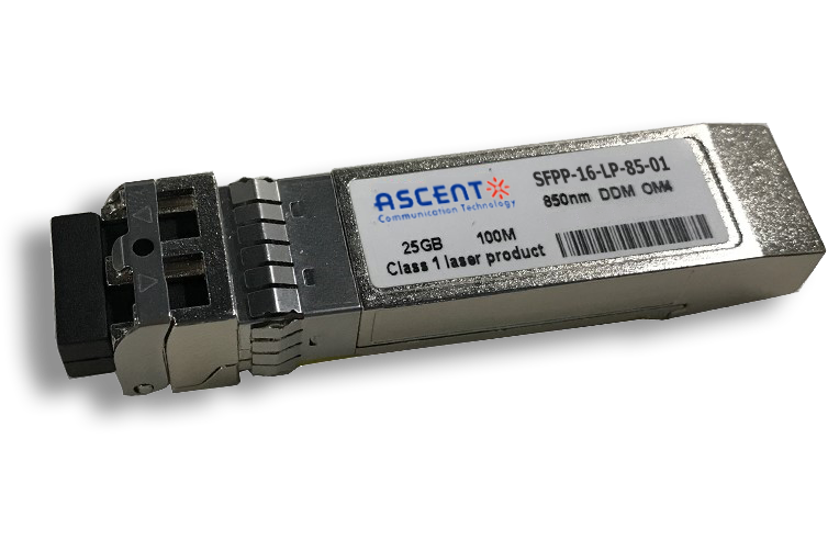
16G SFP+ FC 850 nm 100 m
8.5G SFP+ SR 850 nm 150 m
6.25G SFP+ LRM 1330 nm 2 km
6.25G SFP+ SR 850 nm 300 m