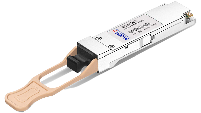
The QSFP-40-CSR4-03 transceiver is a high-performance, cost-effective solution for short-reach 40 Gigabit Ethernet connectivity. Designed to operate over multimode fiber (MMF), it supports transmission distances of up to 300 meters on OM3 and 400 meters on OM4 fiber using MTP/MPO-12 connectors. This transceiver module is ideal for data center and enterprise core networks, providing seamless 40G links between switches, routers, and aggregation layers without sacrificing reliability or performance. Built to industry standards, the QSFP-40G-CSR4 Compatible module uses 4x10G lanes (parallel optics) to deliver an aggregate 40G throughput, allowing backward compatibility with 10G networks using breakout cables. It features digital diagnostics monitoring (DDM) for real-time status updates on parameters such as temperature, voltage, and optical power. The module complies with QSFP MSA, SFF-8436, IEEE 802.3ba 40GBASE-SR4, and RoHS-6. With its plug-and-play design, low power consumption, and high reliability, this transceiver is widely used in short-distance server-to-switch connections, rack-to-rack fiber runs, and data center interconnects (DCI).
· QSFP+ MSA compliant
· 4x10Gb/s electrical interface
· Supports 41.2Gb/s aggregate bit rate
· Up to 300m on OM3 MMF
· Single 1x12 MPO receptacle
· Hot-pluggable QSFP+ footprint
· Quad channel full-duplex transceiver module
· Commercial case temperature: 0°C to 70°C
· Single 3.3V power supply
· Maximum power consumption 1 Watt
· Support Digital Diagnostic Monitor interface
· Unretimed XLPPI electrical interface
Absolute Maximum Ratings
It has to be noted that the operation in excess of any individual absolute maximum ratings might cause permanent
damage to this module.
Parameter | Symbol | Min | Typ. | Max | Unit | Note |
Maximum Supply Voltage | Vcc | 0 | 3.6 | V | ||
Storage Temperature | Ts | -40 | 85 | °C | ||
Relative Humidity | RH | 0 | 85 | % |
Recommended Operating Conditions
Parameter | Symbol | Min | Typ. | Max | Unit | Note |
Operating Case Temperature | Tcase | 0 | 70 | °C | ||
Supply Voltage | Vcc | 3.135 | 3.3 | 3.465 | V | |
Relative Humidity | RH | 5 | 85 | % | ||
Data Rate (Optical) | DRo | 4*10.3125 | Gbps | |||
Data Rate (Electrical) | DRE | 4*10.3125 | Gbps | |||
Operating Distance | LD | 300(OM3) | m |
Electrical Characteristics (EOL, TOP = 0 ~70°C ,VCC = 3.135 to 3.465 V)
Parameter | Symbol | Min. | Typ. | Max. | Unit | Note |
Power Consumption | 1 | W | ||||
Supply Current | Icc | 300 | mA | |||
Transmitter | ||||||
Data Rate, each Lane | 10.3125 | Gbps | ||||
Differential Voltage Pk-Pk | Vpp | 900 | mV | |||
Input Differential Impedance | Rin | 100 | Ohm | 1 | ||
Differential Termination Resistance Mismatch | 10 | % | ||||
Receiver | ||||||
Data Rate, each lane | 10.3125 | Gbps | ||||
Output Differential Impedance | Rout | 100 | Ohm | |||
Differential Termination Resistance Mismatch | 10 | % | ||||
Differential Output Voltage | Vout, pp | 900 | mV | 2 | ||
1. Connected directly to TX data input pins, AC coupled thereafter.
2. Into 100Q differential termination.
Parameter | Symbol | Min. | Typ. | Max. | Unit | Notes |
Transmitter(per Lane) | ||||||
Average Output Power | POUT | -7.6 | 2.4 | dBm | ||
Transmit OMA per Lane | TxOMA | -5.6 | 3.0 | dBm | 1 | |
Extinction Ratio | ER | 3.0 | dB | |||
Center Wavelength | λ | 840 | 850 | 860 | nm | |
RMS Spectral Width | σ | 0.65 | nm | |||
Transmitter and Dispersion Penalty | TDP | 3.5 | dB | |||
Transmitter OFF Output Power | POff | -30 | dBm | |||
Transmitter Eye Mask Definition {X1,X2,X3,Y1,Y2,Y3} | 0.23,0.34,0.43,0.27,0.35,0.4 | |||||
Receiver(per Lane) | ||||||
Input Optical Wavelength | λ | 840 | 850 | 860 | nm | |
Rx Sensitivity per Lane | RSENS | -9.5 | dBm | 2 | ||
Input Saturation Power (Overload) | PSAT | +2.4 | dBm | |||
Receiver Reflectance | Rfl | -12 | dBm | |||
Loss of Signal Assert | PA | -30 | dBm | |||
Loss of Signal De-assert | PD | -12 | dBm | |||
LOS Hysteresis | PD - PA | 0.5 | 6 | dB | ||
1. Even if TDP is<0.9dB, the OMA min must exceed this value.
2. Sensitivity is specified at BER@1E-12.
Digital Diagnostic Monitoring Functions
Parameter | Symbol | Min. |
Case Temperature | ±3 | °C |
Supply Voltage | ±3% | V |
Tx Bias Current | ±10% | mA |
Tx Optical Power | ±3 | dB |
Rx Optical Power | ±3 | dB |


64G SFP56 850nm 100m
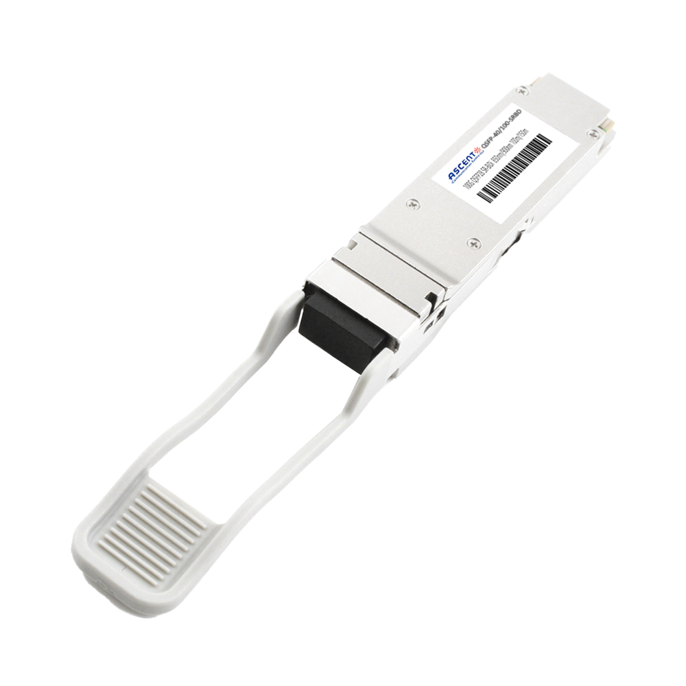
40/100G SFP28 SWDM4 100m

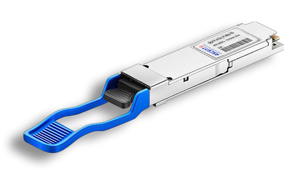
40G QSFP+ ER4 Industrial 40 km

40G QSFP+ ER4 40 km

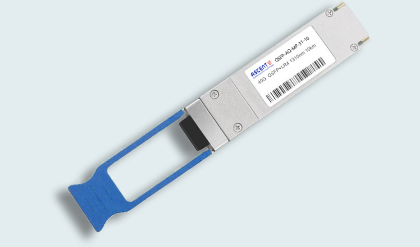
40G QSFP+ LR4 Industrial 10 km

40G QSFP+ LR4 10 km

40G QSFP+ PSM4 2 km
40G QSFP+ PLR4 1310 nm 10 km
40GBASE-UNIV QSFP+ MMF and SMF
40G QSFP+ CWDM 2 km
40G QSFP CWDM 20 km
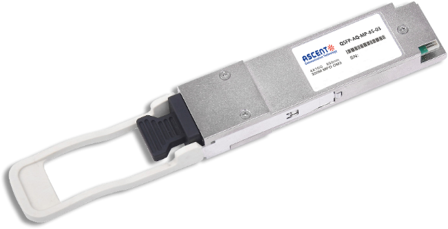
40G QSFP+ SR4 300 m

40G QSFP+ BIDI 150m
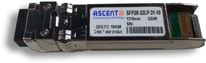
32G SFP28 1310 nm 10 km

32G SFP28 SR 850 nm 100 m
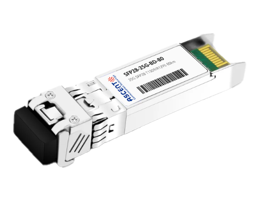
25G SFP28 BIDI 80 km
.png)
25G SFP28 CWDM 10 km(E)
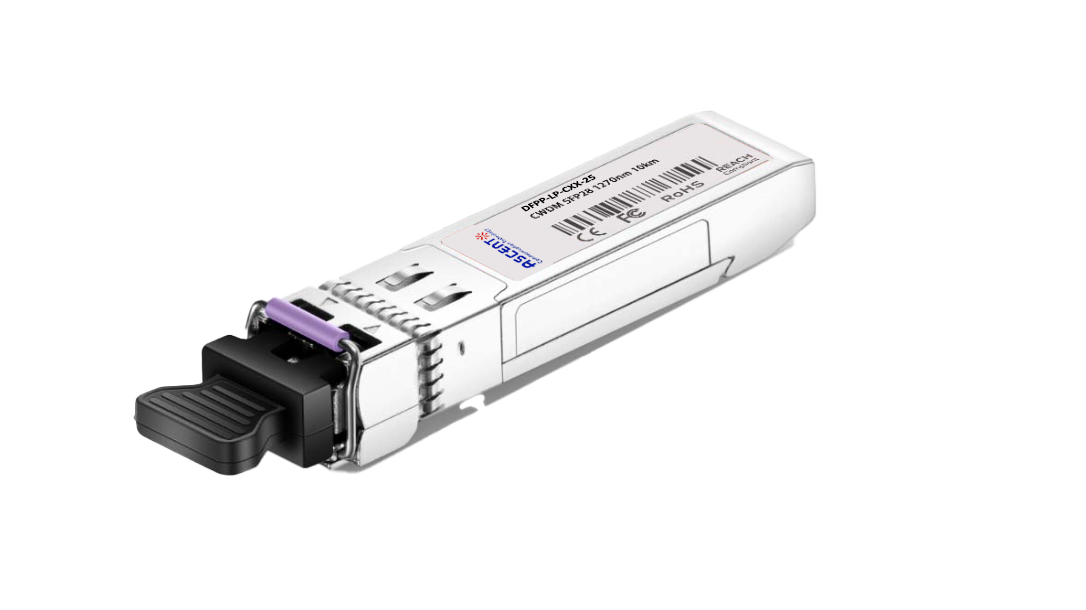
25G SFP28 CWDM 10 km(D)

25G SFP28 ZR 1310nm 80km
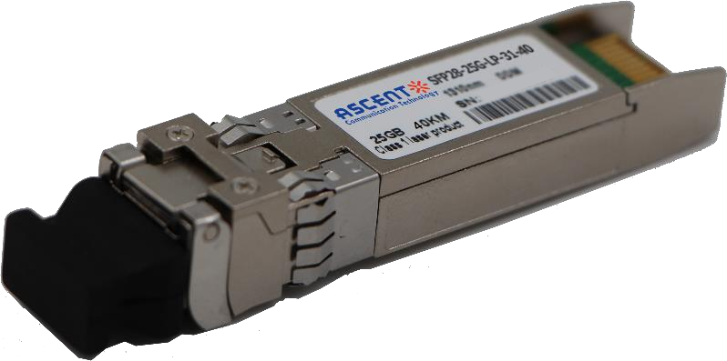
25G SFP28 1310 nm 40km
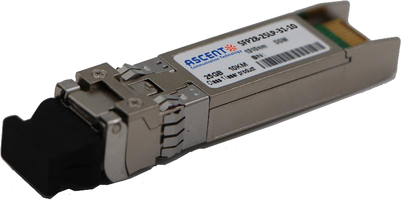
25G SFP28 1310 nm 10 km
25G SFP28 850 nm 300m

10/25G SFP28 1310nm 40km

10/25G SFP28 1310nm 10km

10/25G SFP28 850 nm 300m

10/25G SFP28 850 nm 100m