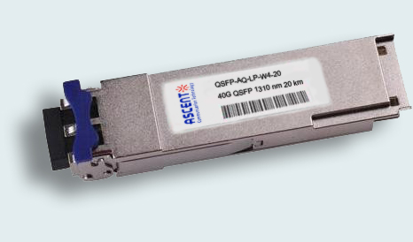
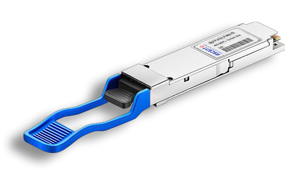
Ascent’s QSFP-AQ-LP-W4-20 is a QSFP transceiver designed to operate over single-mode fiber using 4x10 CWDM channels in 1310 band for data links up to 20 km. The module converts 4 inputs channel of 10 Gb/s electrical data to 4 CWDM optical signals, and multiplexes them into a single channel for 40 Gb/s optical transmission. On the receiver side, the module optically de-multiplexes a 40 Gb/s input into 4 CWDM channels signals, and converts them to 4 channel output electrical data.
• 4 CWDM lanes Mux/Demux design
• Up to 11.1 Gbps Data rate per wavelength
• Up to 20 km transmission on SMF
• Electrically hot-pluggable
• Digital Diagnostics Monitoring Interface
• Compliant with QSFP+ MSA with LC connector
• Case operating temperature range:0 °C to 70°C
• Power dissipation < 2.5 W
• Compliant to IEEE802.3ba
• Compliant to SFF-8436
• RoHS compliant
Absolute Maximum Ratings
Parameter | Symbol | Min. | Typ. | Max. | Unit | Note |
Storage Temperature | Ts | ‑40 | ‑ | 85 | °C | |
Relative Humidity | RH | 5 | ‑ | 95 | % | |
Power Supply Voltage | VCC | ‑0.3 | ‑ | 4 | V | |
Signal Input Voltage | Vcc‑ | ‑ | Vcc+0. | V |
Recommended Operating Conditions
Parameter | Symbol | Min. | Typ. | Max. | Unit | Note |
Case Operating Temperature | Tcase | 0 | ‑ | 70 | °C | Without air |
Power Supply Voltage | VCC | 3.1 | 3.3 | 3.47 | V | |
Power Supply Current | ICC | ‑ | 760 | mA | ||
Data Rate | BR | 10.31 | Gbp | Each | ||
Transmission Distance | TD | ‑ | 20 | km | ||
Coupled fiber | Single‑mode fiber | 9/125 µm | ||||
Optical Characteristics
Parameter | Symbol | Min. | Typ. | Max. | Unit | Note |
Transmitter | ||||||
Wavelength | λ0 | 1264.5 | 1271 | 1277.5 | nm | |
λ1 | 1284.5 | 1291 | 1297.5 | nm | ||
λ2 | 1304.5 | 1311 | 1317.5 | nm | ||
λ3 | 1324.5 | 1331 | 1337.5 | nm | ||
Total Output Power | POUT | 8.3 | dBm | |||
Average Launch Power per lane | ‑7 | 2.3 | dBm | |||
Spectral Width (‑20 dB) | σ | 1 | nm | |||
SMSR | 30 | dB | ||||
Optical Extinction Ratio | ER | 3.5 | dB | |||
Average Launch Power Off per Lane | POFF | ‑30 | dBm | |||
RIN | RIN | ‑128 | dB/Hz | |||
Output Eye Mask | Compliant with IEEE 802.3ba | |||||
Receiver | ||||||
Rx Sensitivity per Lane (OMA) | RSENS | ‑13.7 | dBm | 1 | ||
Input Saturation Power (Overload) | Psat | 2.3 | dBm | |||
Receiver Reflectance | Rr | ‑26 | dB | |||
Notes:
1. Measured with a PRBS 231‑1 test pattern, @10.325 Gb/s, BER<10‑12.
Electrical Characteristics
Parameter | Symbol | Min. | Typ. | Max. | Unit | Note |
Supply Voltage | Vcc | 3.13 | 3.3 | 3.47 | V | |
Supply Current | Icc | 760 | mA | |||
Transmitter | ||||||
Input Differential Impedance | Rin | 100 | Ω | 1 | ||
Differential Data Input Swing | Vin, pp | 180 | 1000 | mV | ||
Transmit Disable Voltage | VD | Vcc‑1.3 | Vcc | V | ||
Transmit Enable Voltage | VEN | Vee | Vee+0.8 | V | 2 | |
Transmit Disable Assert Time | 10 | µs | ||||
Receiver | ||||||
Differential Data Output Swing | Vout, pp | 300 | 850 | mV | 3 | |
Data Output Rise Time | tr | 28 | ps | 4 | ||
Data Output Fall Time | tf | 28 | ps | 4 | ||
LOS Fault | VLOSfault | Vcc‑1.3 | VccHOST | V | 5 | |
LOS Normal | VLOS | Vee | Vee+0.8 | V | 5 |
Notes:
1. Connected directly to TX data input pins. AC coupled thereafter.
2. Or open circuit.
3. Into 100 Ω differential termination.
4. 20 % to 80 %.
5. Loss Of Signal is LVTTL. Logic 0 indicates normal operation; logic 1 indicates no signal detected.


64G SFP56 850nm 100m
40/100G SFP28 SWDM4 100m

40G QSFP+ ER4 Industrial 40 km

40G QSFP+ ER4 40 km

40G QSFP+ LR4 Industrial 10 km

40G QSFP+ LR4 10 km

40G QSFP+ PSM4 2 km
40G QSFP+ PLR4 1310 nm 10 km
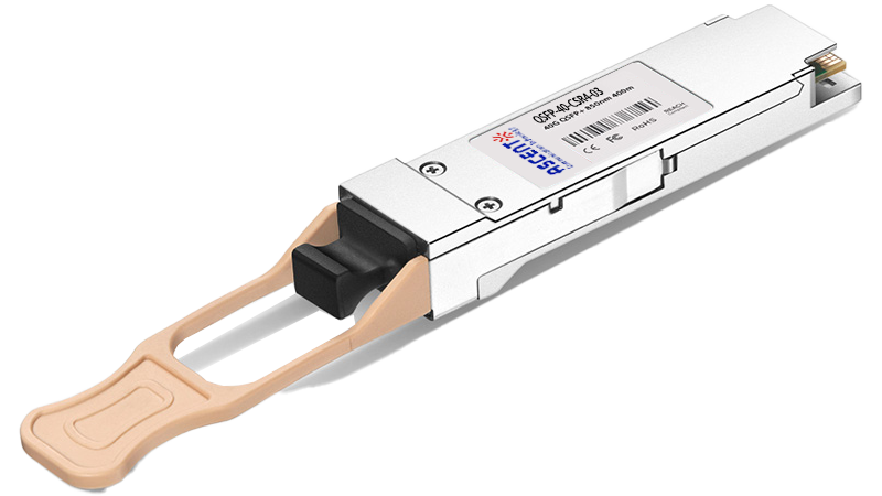
40G QSFP+ CSR4 300m
40GBASE-UNIV QSFP+ MMF and SMF
40G QSFP+ CWDM 2 km
40G QSFP+ SR4 300 m

40G QSFP+ BIDI 150m
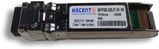
32G SFP28 1310 nm 10 km

32G SFP28 SR 850 nm 100 m
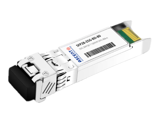
25G SFP28 BIDI 80 km
.png)
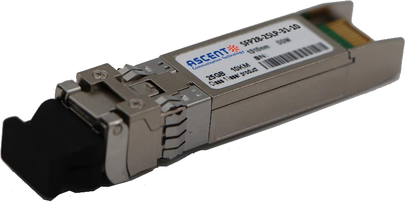
25G SFP28 CWDM 10 km(E)
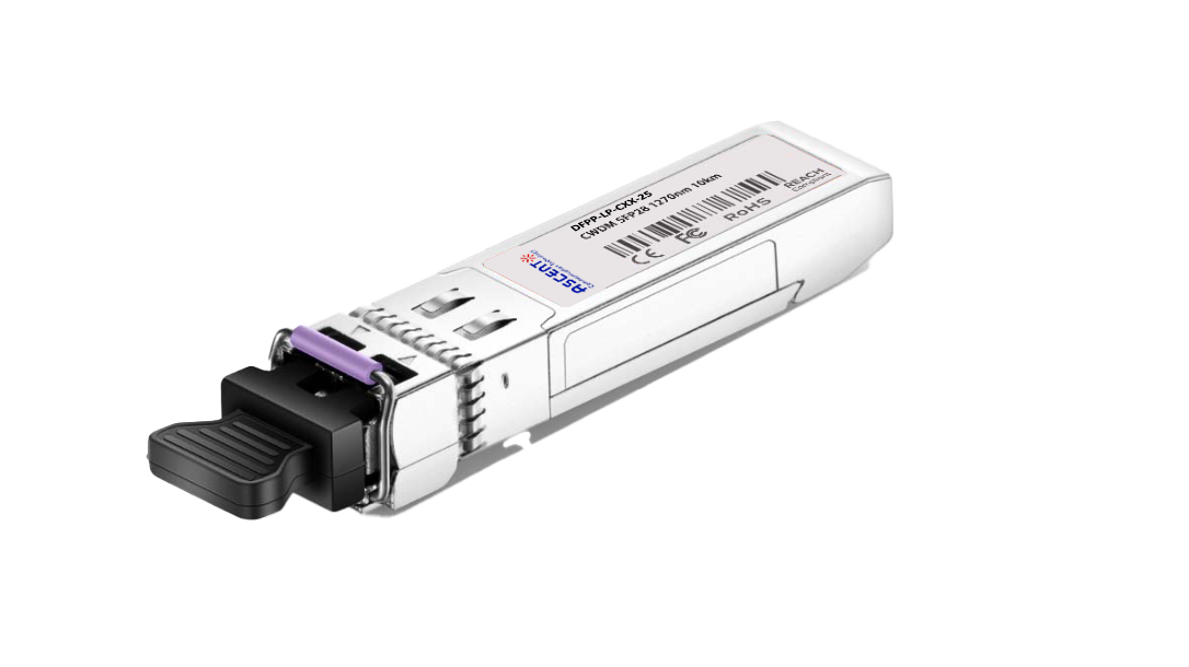
25G SFP28 CWDM 10 km(D)

25G SFP28 ZR 1310nm 80km
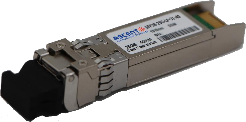
25G SFP28 1310 nm 40km
25G SFP28 1310 nm 10 km
25G SFP28 850 nm 300m

10/25G SFP28 1310nm 40km

10/25G SFP28 1310nm 10km

10/25G SFP28 850 nm 300m

10/25G SFP28 850 nm 100m